Process Control Block Diagram:
The primary objective of industrial process control is to control physical parameters such as temperature, pressure, flow rate, level, force, light intensity, and so on. The Process Control Block Diagram is designed to maintain these parameters near some desired specific value. As these parameters can change either spontaneously or because of external influences, we must constantly provide corrective action to keep these parameters constant or within the specified range.
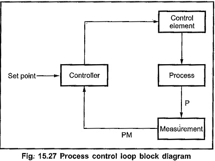
Fig. 15.27 shows the Process Control Block Diagram elements are :
-
Process
-
Measurement
-
Controller
-
Control Element
To control process parameter, we must know the value of that parameter and hence it is necessary to measure that parameter. In general, a measurement refers to the transduction of the process parameter into some corresponding Analog Interfacing of the parameter, such as a pneumatic pressure, an electric voltage, or current. A transducer is a device that performs the initial measurement and energy conversion of a process parameter into analogous electrical or pneumatic information. Many times further transformation or signal conditioning may be required to complete the measurement function.
The Fig. 15.27 shows parameter P and its measured value PM. The measured value is compared with the set value (desired value). According to the result of the comparison the control action is determined and the control signal is generated. The controller does this work. Finally, the control signal is used to provide necessary changes in the process parameter with the help of control element.
In most of the process control applications, the electronic instruments and controllers are used to measure and evaluate the process parameter. Thus, the control signal generated by the electronic controller is either Analog Interfacing or digital, which is not directly useful to change the process parameter as desired. For example, Analog Interfacing or digital signal from the electronic controller cannot do the opening and closing of the valve. For operation of valve, the device called actuator is used.
An actuator is a device which converts the control, signal into physical action like action of opening or closing the valve. The actuator like DC motor is necessary to operate the control valve. To operate DC motor it is necessary to convert control signal from the electronic controller into signal which can operate the DC motor. The step involved in the corrective action are shown in Fig. 15.28, with the help of block diagram.
The signal converter converts the control signal in proper form such that it can drive actuator. In this case control signal is converted into proportional DC signal which can drive the DC motor, actuator. The actuator then translates the control signal into action and operates final control elements valve to change the process parameter to the desired value.
In this section, we see the interfacing circuits for some transducers and sensors which are used to sense and convert the physical parameters into their corresponding electrical equivalent parameters such as voltage or current. We also discuss the applications such as microcomputer based scale and temperature control system.
Microprocessor Based Scale:
In this section, we see the entire process of reading a physical parameter and displaying it on the digital display. For this, we discuss a commonly used microprocessor based scale.
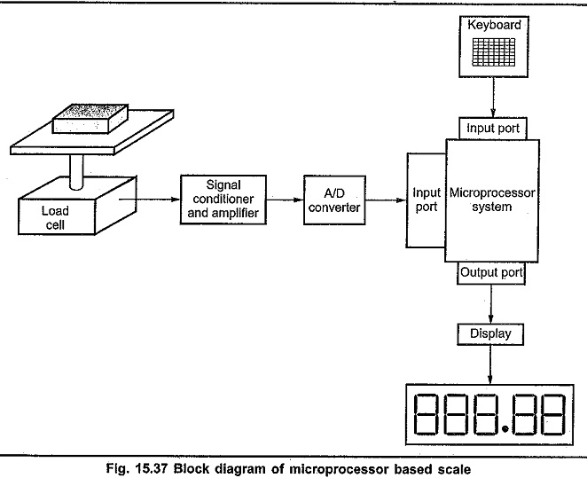
The Fig. 15.37 shows a block diagram of microprocessor based scale. It consists of load cell, suitable signal conditioner, Analog Interfacing to digital converter and output indicator in the form of 7-segment display.
The load cells (which may be up to 4 or 8 cells) convert the weight data into electrical signal which is amplified to give an output of 0 to 5V. This signal is converted into digital form using- A/D converter. Microprocessor system accepts this digital data through input port. Using calibration procedure microprocessor system convert this digital data into actual weight data. It finds the 7-segment codes to display the actual weight on the display.
Microprocessor system also gets the item code from the keyboard. It refers lookup table to get the item-price and calculate the net price from the actual Weight and item-price. After determining the net price the processor displays the actual weight and net price to be paid on the 7-segment display.


