Radio Receivers Articles:
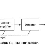
Tuned Radio Frequency Receiver: The Tuned Radio Frequency Receiver is a simple “logical” receiver. A person with just a little knowledge of communications would probably expect all radio receivers to have this form. The virtues of this type, which is now … (Read More)
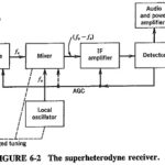
Superheterodyne Principle: The block diagram of Figure 6-2 shows a basic superheterodyne receiver. In the Superheterodyne Principle, the incoming signal voltage is combined with a signal generated in the receiver. This local oscillator voltage is normally converted into a signal of … (Read More)
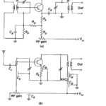
Transistor RF Amplifier Circuit: A radio receiver always has an RF section, which is a tunable circuit connected to the antenna terminals. It is there to select the wanted frequency and reject some of the unwanted frequencies. However, such a receiver … (Read More)
Frequency Changing and Tracking in Receivers: The mixer is a nonlinear device having two sets of input terminals and one set of output terminals. The signal from the antenna or from the preceding RF amplifier is fed to one set of … (Read More)
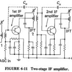
Intermediate Frequency Amplifier: Choice of frequency: The Intermediate Frequency Amplifier (IF) of a receiving system is usually a compromise, since there are reasons why it should be neither low nor high, nor in a certain range between the two. The following are … (Read More)
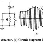
Simple Diode Detector: Operation of diode detector: The Simple Diode Detector is by far the most common device used for AM demodulation (or detection), and its operation will now be considered in detail. On the circuit of Figure 6-12a, C is … (Read More)
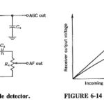
Working Principle of Automatic Gain Control: Working Principle of Automatic Gain Control is a system by means of which the overall gain of a radio receiver is varied automatically with the changing strength of the received signal, to keep the output … (Read More)
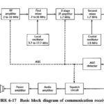
Communication Receiver Block Diagram: A Communication Receiver Block Diagram is one whose main function is the reception of signals used for communications rather than for entertainment. It is a radio receiver designed to perform the tasks of low- and high-frequency reception … (Read More)
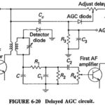
Delayed Automatic Gain Control: Simple AGC is clearly an improvement on no AGC at all, in that the gain of the receiver is reduced for strong signals. Unfortunately, as Figures 6-14 and 6-19 both show, even weak … (Read More)
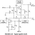
Squelch Circuit: Squelch (muting): When no carrier is present at the input, i.e., in the absence of transmissions on a given channel or between stations, a sensitive receiver will produce a disagreeable amount of loud noise. This is because AGC disappears in … (Read More)
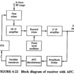
Automatic Frequency Control Block Diagram: As previously we see, the heart of an AFC circuit is a frequency-sensitive device, such as the phase discriminator, which produces a dc voltage whose amplitude and polarity are proportional to the amount … (Read More)
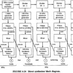
Direct Synthesizer Block Diagram: A Direct Synthesizer Block Diagram is a piece of apparatus in which multiples and submultiples of a single crystal oscillator frequency are combined by addition and/or subtraction to provide a very wide selection of stable output frequencies. … (Read More)
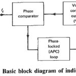
Indirect Synthesizer: The required frequency range in most synthesizers nowadays is obtained from a variable voltage-controlled oscillator (VCO), whose output is corrected by comparison with that of a reference source. This inbuilt source is virtually a direct synthesizer. As … (Read More)
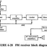
FM Receiver Block Diagram: The FM receiver is a superheterodyne receiver, and the FM Receiver Block Diagram of Figure 6-28 shows just how similar it is to an AM receiver. The basic differences are as follows: Generally much higher operating frequencies in … (Read More)
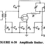
Amplitude Limiter in FM Receiver: In order to make full use of the advantages offered by FM, a demodulator must be preceded by an Amplitude Limiter in FM Receiver, as discussed earlier, on the grounds that any amplitude changes in the … (Read More)
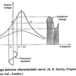
Slope Detector FM Demodulation: Consider a frequency-modulated signal fed to a tuned circuit whose resonant frequency is to one side of the center frequency of the FM signal. The output of this tuned circuit will have an amplitude that depends on … (Read More)
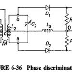
Phase Discriminator: This Phase Discriminator is also known as the center-tuned discriminator or the Foster-Seeley discriminator, after its inventors. It is possible to obtain the same S-shaped response curve from a circuit in which the primary and the secondary windings are … (Read More)
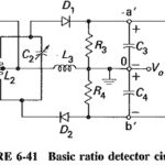
Ratio Detector Circuit: In the Foster-Seeley discriminator, changes in the magnitude of the input signal will give rise to amplitude changes in the resulting output voltage. This makes prior limiting necessary. It is possible to modify the discriminator circuit to provide … (Read More)
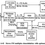
Stereo FM Multiplex Reception: Assuming there have been no losses or distortion in transmission, the demodulator output in a Stereo FM Multiplex Reception, tuned to a stereo transmission, will be exactly as shown in Figure 5-10. Increasing in frequency, the signal … (Read More)
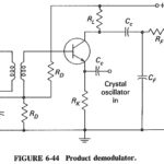
Product Demodulator: The Product Demodulator (or detector), as shown in Figure 6-44, is virtually a mixer with audio output. It is popular for SSB, but is equally capable of demodulating all other forms of AM. hi the circuit shown, the input … (Read More)
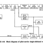
Receiver Types: There are Two Receiver Types namely, Pilot Carrier Receiver and a Suppressed Carrier Receiver; the suppressed carrier receiver incorporates a frequency synthesizer for extra stability and also is used to show how ISB may be demodulated. Pilot Carrier Single Sideband … (Read More)
