RC Phase Shift Oscillator Using Op amp:
RC Phase Shift Oscillator basically consists of an amplifier and a feedback network consisting of resistors and capacitors arranged in ladder fashion. Hence such an oscillator is also called Ladder Type RC Phase Shift Oscillator.
Basic RC Circuit:
To understand the operation of this Oscillator, let us study Basic RC Circuit, which is used in the feedback network of this oscillator. The Fig. 2.90 shows the Basic RC Circuit.
The capacitor C and resistance R are in series. Now XC is the capacitive reactance in ohms given by,
The total impedance of the circuit is,
The r.m.s. value of the input voltage applied is say Vi volts. Hence the current is given by,
where
and
From expression of current it can be seen that current I leads input voltage Vi by angle Φ.
The output voltage Vo is the drop across resistance R given by,
The voltage across the capacitor is,
The drop VR is in phase with current I while the drop VC lags current I by 90° i.e. I leads VC by 90°. The phasor diagram is shown in the Fig. 2.90 (b).
By using proper values of R and C, the angle Φ is adjusted in practice equal to 60°
Feedback Network in RC Phase Shift Oscillator:
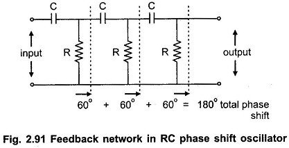
As stated earlier, RC network is used in feedback path. In oscillator, feedback network must introduce a phase shift of 180° to obtain total phase shift around a loop as 360°. Thus if one RC network produces phase shift of Φ = 60° then to produce phase shift of 180° such three RC networks must be connected in cascade.
Hence Feedback Network in RC Phase Shift Oscillator consists of three RC sections each producing a phase shift of 60°, thus total phase shift due to feedback is 180° (3 x 60°). Such a feedback network is shown in the Fig. 2.91.
The network is also called the ladder network. All the resistance values and all the capacitance values are same, so that for a particular frequency, each section of R and C produces a phase shift of 60°.
RC Phase Shift Oscillator Using Op amp:
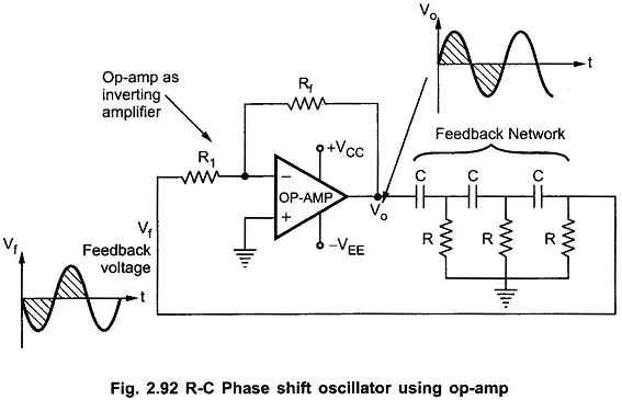
R-C phase shift oscillator using op-amp uses op-amp in inverting amplifier mode. Thus it introduces the phase shift of 180° between input and output. The feedback network consists of 3 RC sections each producing 60° phase shift. Such a RC phase shift oscillator using op-amp is shown in the Fig. 2.92.
The output of amplifier is given to feedback network. The Output of feedback network drives the amplifier. The total phase shift around a loop is 180° of amplifier and 180° due to 3 RC section, thus 360°. This satisfies the required condition for positive feedback and circuit works as an oscillator.
The frequency of sustained oscillations generated depends on the values of R and C and is given by,
The frequency is measured in Hz.
At this frequency the gain of the op-amp must be at least 29 to satisfy Aβ = 1.
Now gain of the op-amp inverting amplifier is given by,
Thus circuit will work as an oscillator which will produce a sinusoidal waveform if gain is 29 and total phase shift around a loop is 360°. This satisfies the Barkhausen criterion for the oscillator. These oscillators are used over the audio frequency range i.e. about 20 Hz upto 100 kHz.
Advantages of RC Phase Shift Oscillator:
The Advantages of RC Phase Shift Oscillator are,
- The circuit is simple to design.
- Can produce output over audio frequency range.
- Produces sinusoidal output waveform.
- It is a fixed frequency oscillator.
Disadvantages of RC Phase Shift Oscillator:
By changing the values of R and C, the frequency of the oscillator can be changed. But the values of R and C of all three sections must be changed simultaneously to satisfy the oscillating conditions. But this is practically impossible. Hence the phase shift oscillator is considered as a fixed frequency oscillator, for all practical purposes.
And the frequency stability is poor due to the changes in the values of various components, due to effect of temperature, ageing etc.


