Resonance Articles:
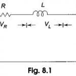
Series Resonance Circuit: In many electrical circuits, resonance is a very important phenomenon. The study of resonance is very useful, particularly in the area of communications. For, example, the ability of a radio receiver to select a certain … (Read More)
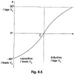
Impedance and Phase Angle of Series Resonant Circuit: The impedance of a Series Resonant Circuit is The variation of XC and XL with frequency is shown in Fig. 8.4. At zero frequency, both XC and Z are infinitely large, and XL is zero because … (Read More)
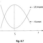
Voltage and Current in Series Resonant Circuit: The variation of impedance and current with frequency of Voltage and Current in Series Resonant Circuit is shown in Fig. 8.7. At resonant frequency, the capacitive reactance is equal to inductive reactance, and hence the … (Read More)
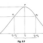
Bandwidth of RLC Circuit: The bandwidth of any system is the range of frequencies for which the current or output voltage is equal to 70.7% of its value at the resonant frequency, and it is denoted by BW. Figure 8.9 shows … (Read More)
Voltage Magnification in Series Resonance: If we assume that the voltage applied to the series RLC circuit is V, and the current at resonance is I, then the voltage across L is VL = IXL = (V/R) … (Read More)
Parallel RLC Circuit Resonance: Basically, parallel resonance occurs when XC = XL. The frequency at which resonance occurs is called the resonant frequency. When XC = XL, the two branch currents are equal in magnitude and 180° … (Read More)
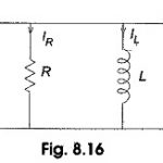
Quality Factor of Parallel RLC Circuit: Consider the Quality Factor of Parallel RLC Circuit shown in Fig. 8.16. In the circuit shown, the condition for resonance occurs when the susceptance part is zero. Admittance The frequency at which resonance occurs is The voltage and current … (Read More)
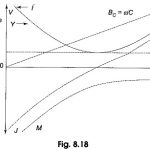
Current Magnification in Parallel Resonance: Current Magnification in Parallel Resonance occurs when the voltage applied to the parallel circuit, V=IR Since For the Capacitor, Therefore, the quality factor Qr = IL/I or IC/I Reactance curves in Parallel Resonance: The effect of variation of frequency on the reactance … (Read More)
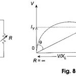
Locus Diagram of RL Series Circuit: To discuss the basis of representing a Locus Diagram of RL Series Circuit by means of a circle diagram consider the circuit shown in Fig. 8.19(a). The analytical procedure is greatly simplified by assuming that … (Read More)
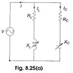
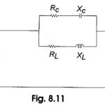
Locus Diagram of Parallel RLC Circuit: (a) Variable XL – Locus plots are drawn for parallel branches containing RLC elements in a similar way as for series circuits. Here we have more than one current locus. Consider the Locus Diagram of … (Read More)