Rotating Machines Articles:
Rotating Electrical Machines: We Know that electromechanical energy conversion takes place whenever a change in flux is associated with mechanical motion. Speed voltage is generated in a coil when there is relative movement between the coil and magnetic field. Alternating emf … (Read More)
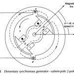
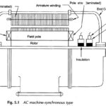
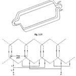
Synchronous Machine Working Principle: Figure 5.2 shows the simplified version of an ac Synchronous Machine Working Principle with a 2-pole field winding on the rotor and a single coil aa’ on the stator. This type of rotor poles are known as … (Read More)
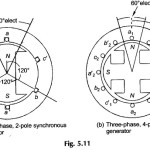
Three Phase Synchronous Generator: Practical synchronous generators are always of the 3-phase kind because of the well-known advantages of a 3-phase system. If two coils were located at two different space locations in the stator of Fig. 5.2, their emfs will … (Read More)
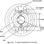
2 Pole Elementary DC Machine: Figure 5.13 shows a 2 Pole Elementary DC Machine with a single coil rotating armature. It may be seen that the field winding is stationary with salient poles whose pole-shoes occupy a major part of the … (Read More)
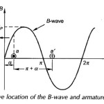
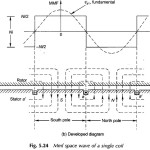
EMF Equation of AC Winding: The B-wave of a EMF Equation of AC Winding synchronous machine (in general multi-polar) assumed sinusoidal is drawn in Fig. 5.15 and a single full-pitched coil (coil-side space separation π rad (180°) elect.) is shown in … (Read More)
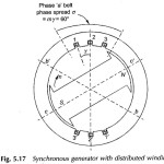
Synchronous Generator with Distributed Winding: Synchronous Generator with Distributed Winding – It may be seen from Eq. (5.7) that the flux/pole is limited by the machine dimensions and the peak flux density which cannot exceed a specified value dictated by saturation … (Read More)
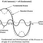
Harmonic Analysis in Distributed Winding: The flux density wave of a synchronous machine is never exactly sine wave. Because of odd symmetry of poles (alternately north-south), the space Harmonic Analysis in Distributed Winding of the B-wave comprises odd harmonics only, which … (Read More)
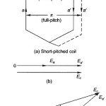
Short Pitch Coil or Chorded Coil: Short Pitch Coil – So far it was assumed that the stator coils are full-pitched (a span of π rad elect). Coils may have a span of less than the full-pitch. This arrangement offers certain … (Read More)
Two layer Winding of Transformer: One important and commonly used way of neatly arranging the end connection of coils in a winding is to place two coil-sides per slot. Each coil then has one coil-side in the bottom half of one … (Read More)
Armature Winding in DC Machine: With reference to the single-coil elementary Armature Winding in DC Machine of Figs 5.13 and 5.14(a) which shows the B-wave of the machine relative to the elementary full-pitched coil, LetConsider that the coil is lying in the … (Read More)
MMF of AC Distributed Winding: It has been seen earlier that the armature what-when-how.comof a practical machine has distributed winding wound for the same number of poles as the field winding. As the armature carries current, the resultant field of its … (Read More)
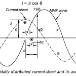
Sinusoidally Distributed Current Sheet Concept: It was seen above that a distributed winding gives rise to a stepped mmf wave having a strong fundamental component which will be considered in machine modelling while all the harmonic components will be neglected (justification … (Read More)
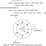
Rotating Magnetic Field: Rotating Magnetic Field – It was seen earlier that the sinusoidal current in any phase of an ac winding produces a pulsating mmf wave in space whose amplitude varies sinusoidally with time. The expression for the fundamental component … (Read More)
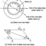
Torque in Round Rotor Synchronous Machine: Torque in Round Rotor Synchronous Machine – When the stator and rotor windings of a machine both carry currents, they produce their own magnetic fields along their respective axes which are sinusoidally distributed along the … (Read More)
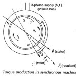
Torque Equation of Synchronous Motor: Figure 5.36 shows a Torque Equation of Synchronous Motor with a round rotor. The rotor is initially stationary with fixed north-south poles created by dc excitation. Let the 3-phase winding of the stator be connected to … (Read More)
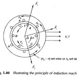
Principle of Induction Motor | Torque Slip Characteristic: Principle of Induction Motor has not been introduced so far. Consider a cylindrical rotor machine with both the stator and rotor wound for three phases and identical number of poles as shown in … (Read More)
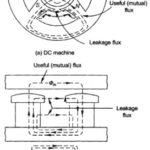
Types of Magnetic Leakage Flux in Induction Motor: The Magnetic Leakage Flux in Induction Motor is that flux which links only the stator or only the rotor windings. Because of the presence of air-gap in the magnetic circuit of machines, the … (Read More)
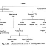
DC Motor Losses and Efficiency: The Losses and Efficiency of a transformer have been studied in earlier lesson. As in the case of transformers, it is more accurate to determine the DC Motor Losses and Efficiency rather than by the direct … (Read More)
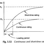
Synchronous Generator Ratings and Loss Dissipation: The Synchronous Generator Ratings and Loss Dissipation is its operating voltage, frequency, speed and kVA/MVA output at a specified power factor. In case of motors the output rating is given in kW (older practice was … (Read More)
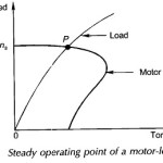
Electric Motor Characteristics: The machine and the load are the two components of an electro-mechanical energy-conversion system, and the Electric Motor Characteristics, generally, play a predominant part in the operating behavior of the complete system. In choosing an electric motor its speed-torque … (Read More)