Megger Circuit Diagram
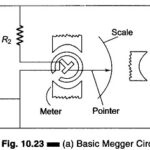
Megger Circuit Diagram: Another common method of measuring resistances above 50 M Ω is the Megger Circuit Diagram (megaohmmeter) shown in Fig. 10.23(a). This instrument is used to measure very…
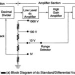
DC Standard Differential Voltmeter: A basic DC Standard Differential Voltmeter can be operated in different modes. The three basic modes of operation are as a dc voltage standard, as a…
Voltage Stability Analysis: The voltage stability analysis for a given system state involves examining following two aspects. Proximity to voltage instability: Distance to instability may be measured in terms of…
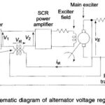
Automatic Voltage Control: Automatic Voltage Control - Figure 8.20 gives the schematic diagram of an automatic voltage regulator of a generator. It basically consists of a main exciter which excites…
Optimal Two Area Load Frequency Control: Modern control theory is applied in this section to design an Optimal Two Area Load Frequency Control for a two-area system. In accordance with…
Turbo Generator Excitation System: Power system operation considered so far was under conditions of steady load. However, both active and reactive power demands are never steady and they continually change…
Phasor Diagram of Synchronous Motor: The Phasor Diagram of Synchronous Motor is the most important element of a power system. It converts mechanical power into electrical form and feeds it…
What is Power Electronic Converter?: What is Power Electronic Converter? - Since the introduction of the thyristor, the Power Electronic Converter technology has progressed through intense technological evolution for the…