UJT Circuit Diagram
UJT Circuit Diagram: UJT Circuit Diagram Operation : The Unijunction transistor (UJT) consists of a bar of lightly-doped n-type silicon with a block of p-type material on one side, [see…
Continue Reading
UJT Circuit Diagram
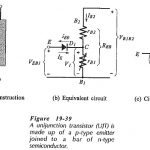
UJT Circuit Diagram: UJT Circuit Diagram Operation : The Unijunction transistor (UJT) consists of a bar of lightly-doped n-type silicon with a block of p-type material on one side, [see…
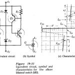
Silicon Bilateral Switch: It might be convenient to think of a Silicon Bilateral Switch (SBS) as an SUS with a gate terminal, or as a low-current TRIAC. However, the SBS is…
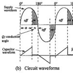
TRIAC Control Circuit Diagram: A TRIAC Control Circuit Diagram that allows approximately 180° of phase control is shown in Fig. 19-27(a). The waveforms in Fig. 19-27(b) illustrate the circuit operation.…
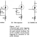
SCR Applications Circuits: SCR Applications Circuits : An SCR circuit is stable when it operates correctly: switching on and off only at the desired instants. Unwanted triggering (also called false…
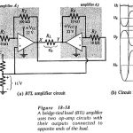
Bridge Tied Load Amplifier: All of the power amplifiers already discussed have been single-ended (SE): meaning that they provide power to a load that has one terminal grounded and the…
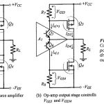
Common Source Power Amplifier Using an Op Amp Driver Stage: Basic Circuit Operation - The Class-AB MOSFET Power Amplifier with OP Amp Driver Stage circuit in Fig. 18-45(a) consists of…
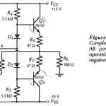
BJT Power Amplifier with Op Amp Driver: BJT Power Amplifier with Op Amp Driver Circuit Operation - The Class-AB power shown in Fig. 18-39 uses an operational amplifier (A1) for…
FET Biasing Articles: DC Load Line for FET: The DC Load Line for FET circuit is drawn on the device output characteristics (or drain characteristics) in exactly the same way…