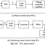
Phase Locked Loop Control
Phase Locked Loop Control(PLL): A PI controller ideally should provide perfect speed regulation. However, due to imperfections in sensing and control circuits, the closed-loop schemes described earlier can at best…
Continue Reading
Phase Locked Loop Control