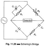
Measurement of Capacitance using Schering Bridge
Measurement of Capacitance using Schering Bridge: A very important bridge used for the precision measurement of capacitors and their insulating properties is the Schering Bridge Experiment. Schering Bridge basic circuit…
Continue Reading
Measurement of Capacitance using Schering Bridge