Capacitor Coupled Two Stage CE Amplifier
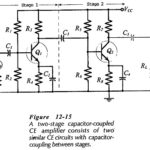
Capacitor Coupled Two Stage CE Amplifier: A Capacitor Coupled Two Stage CE Amplifier circuit is shown in Fig. 12- 15 . Stage-1 is capacitor-coupled (via C3) to the input of…
FET and BJT Difference: FET and BJT Difference (CS, CD, and CG Circuit Comparison) - Table 11-1 compares Zi, Zo and Av for CS, CD, and CG circuits. As already discussed, the…
Transistor Datasheet: To select a transistor for a particular application, the Transistor Datasheet provided by device manufacturers must be consulted. Most data sheets start off with the device type number…
Common Collector Circuit Analysis: In the Common Collector Circuit Analysis (CC) shown in Fig. 6-28 the external load (RL) is capacitor-coupled to the transistor emitter terminal. The circuit uses voltage divider…
Common Emitter Amplifier Circuit: Consider the Common Emitter Amplifier Circuit circuit shown in Fig. 6-17. When the capacitors are regarded as ac short-circuits, it is seen that the circuit input…
Transistor Testing Circuit: In-Circuit Testing - A quick test to check if a transistor is operational can be performed while the device is still connected in a circuit. Consider Fig.…
Traction Drive Rating and Energy Consumption: Traction Drive Rating and Energy Consumption - The speed-time curve of Fig. I0.6(a) is reproduced in Fig. 10.9. For simplification in calculations, it is…
Duty Cycle of Traction Drives: The Duty Cycle of Traction Drives in trains is explained with the help of speed-, torque- and power-time diagrams (Fig. 10.6) which are drawn for…