SCR as Half Wave Rectifier Circuit Diagram
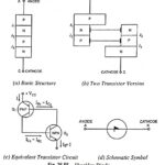
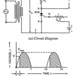
SCR as Half Wave Rectifier Circuit Diagram: SCRs are very useful in ac circuits where they may serve as rectifiers whose output current can be controlled by controlling the gate…
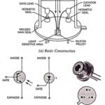
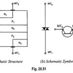
What is Thyristor? - Thyristor Family and its Applications Thyristor is the general name given to a family of semiconductor devices having four layers with a control mechanism, although this…
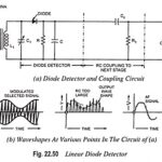
Linear Diode Detector or Envelope Detector: Diode detection is called the envelope detection as it recovers the audio frequency signal envelope from the composite signal. Diode detector is also called…
Generation of DSBSC Signal using Balanced and Ring Modulator: DSBSC signal can be obtained by simply multiplying the modulating signal with the carrier signal. By simple multiplication of Vc sin ωct…
Collector Modulation Circuit - Working, Advantages and Disadvantages: This is very popular method for AM generation. The circuit diagram for collector modulation is shown in Fig. 22.26. Here, the transistor…
Cascaded Differential Amplifier Working Principle: Cascaded Differential Amplifier Working Principle - Figure 20.53 gives an idea of how differential amplifiers can be cascaded to give an op-amp. Here the output…
What is Current Mirror? - Circuit Diagram and its Workings The two-transistor current source, also called a current mirror, is the basic building block in the design of integrated circuit…
Constant Current Bias in Differential Amplifier: In the differential amplifiers discussed so far, we have used the combination of RE and VEE to produce emitter dc bias current. Alternatively, constant…