Common Base Circuit Diagram
Common Base Circuit Diagram: The Common Base Circuit Diagram (CB) shown in Fig. 6-34 is very similar to a CE circuit, except that the input signal is applied to the…
Continue Reading
Common Base Circuit Diagram
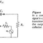
Common Base Circuit Diagram: The Common Base Circuit Diagram (CB) shown in Fig. 6-34 is very similar to a CE circuit, except that the input signal is applied to the…
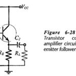
Common Collector Circuit Analysis: In the Common Collector Circuit Analysis (CC) shown in Fig. 6-28 the external load (RL) is capacitor-coupled to the transistor emitter terminal. The circuit uses voltage divider…
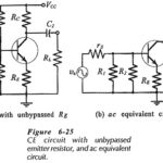
CE Circuit with Unbypassed Emitter Resistor: h-parameter Equivalent Circuit - When an CE Circuit with Unbypassed Emitter Resistor (RE) as shown in Fig. 6-25(a), it is also present in the…
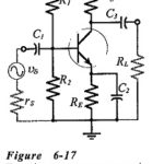
Common Emitter Amplifier Circuit: Consider the Common Emitter Amplifier Circuit circuit shown in Fig. 6-17. When the capacitors are regarded as ac short-circuits, it is seen that the circuit input…
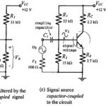
Coupling and Bypassing Capacitors: Coupling Capacitors - To use a transistor circuit to amplify or otherwise process an ac signal, the signal source must be connected to the circuit input.…
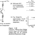
Bias Circuit Thermal Stability: VBE and ICBO Variations - Many transistor circuits are required to operate over a wide temperature range. So, another aspect of bias circuit stability is Bias Circuit…
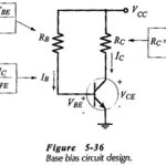
Bias Circuit Design: Bias Circuit Design can be amazingly simple. Usually, it is just a matter of determining the required voltage across each resistor and the appropriate current levels. Then,…
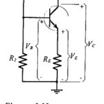
BJT Bias Circuit Troubleshooting: Voltage Measurement - When a BJT Bias Circuit Troubleshooting is constructed in a laboratory situation, the supply voltage (VCC) and the voltage levels at the transistor…