Collector to Base Bias Circuit
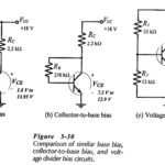
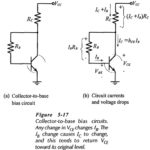
Collector to Base Bias Circuit: The Collector to Base Bias Circuit shown in Fig. 5-17(a) has the base resistor (RB) connected between the transistor collector and base terminals. As will…
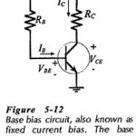
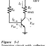
Base Bias in BJT: Circuit Operation and Analysis - The transistor bias arrangement shown in Fig. 5-12 is known as Base Bias in BJT and also as fixed current bias.…
DC Load Line of BJT Biasing Circuit: The DC Load Line of BJT Biasing Circuit is a straight line drawn on the transistor output characteristics. For a common-emitter (CE) circuit,…
DC Motor Drives Articles: Types of DC Motor: The commonly used Types of DC Motor are shown in Fig. 5.1. In a separately excited motor, the field and armature voltages…
Interlocking Components in Electrical Drives: Sensing of signals required for speed and current control loops. Sequencing and interlocking operations are explained in the previous section, whereas this section discusses components…
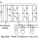
PWM VSI Induction Motor Drive: PWM VSI Induction Motor Drive for traction is shown in Fig. 10.21. A pulsewidth modulated voltage source inverter converts dc into variable frequency and variable…
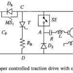
DC Traction using Semiconductor Chopper Controlled DC Motors: Chopper control has replaced resistance control in all dc traction schemes, such as 1500 V dc main line and suburban traction, 750…
Battery Powered Vehicles: Battery Powered Vehicles - These are popularly known as electric vehicles. Although several batteries and fuel cells have been developed, only available at affordable price is the…