Selection of Hydraulic Turbines:
It is very important to select the type of Hydraulic turbine which will give maximum possible efficiency. The Selection of Hydraulic Turbines always match specific conditions under which it has to operate and attain maximum possible efficiency.
The choice of Selection of Hydraulic Turbines depends upon given head and discharge at a particular site of the power plant. If the power to be developed, speed and head are available, then the type of turbine can be determined.
The following factors should be considered for Selection of Hydraulic Turbines.
- Rotational speed of turbine
- Specific speed of turbine
- Maximum efficiency
- Part load efficiency
- Head
- Type of water
- Runaway speed
- Cavitation
- Number of units
- Overall cost
(i) Rotational speed of turbine
Nowadays in all modern hydro power plant to reduce transmission losses, the turbines are directly connected with the generator by means of coupling. This arrangement of coupling narrow down (or) depends upon to the range of speed used for the turbine. The purpose of generator is to generate the power at constant voltage and frequency. To attain constant voltage and frequency, the generator should be operated at synchronous speed. The synchronous speed of generator is given by
where
- Nsync = synchronous speed
- f = frequency
- p = number of pairs of poles used
Therefore, for directly coupled turbines, the turbine has to run at, synchronous speed only. Frequency is more or less fixed (50 to 60 cycles/sec). It always preferable to run generator at high synchronous speed because the number of poles required for generator reduces with increase in synchronous speed which reduces the size of generator.
The major problem with high speed turbine are the cavitation and centrifugal forces acting on turbine parts which requires robust construction. But the overall cost can be reduced by adopting higher rotational speed as by smaller turbine and smaller generator are required to generate the same power produced by larger turbines and larger generator.
(ii) Specific speed of turbine
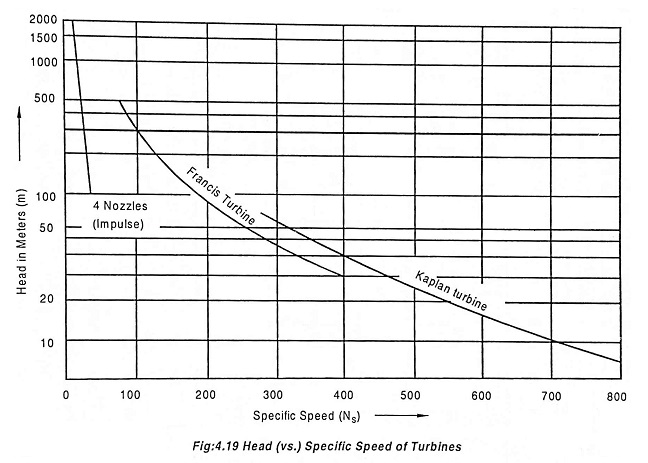
If the head is high for given speed and power output then low specific speed machines such as impulse turbine is required. If the head is low, high specific speed machines such as propeller turbine is required.
The specific speed can be calculated by the equation
The conditions of specific speed to the head of water is drawn as graph with practical observation shows that there is an increase in latitude of specific speed of runners with decrease in head provided and the height of the runner should be above latitude to avoid cavitation.
| Sl. No | Specific Speed | Type of Turbine |
| 1 | 10 to 35 | Pelton wheel with one nozzle |
| 2 | 35 to 60 | Pelton wheel with two (or) more nozzles |
| 3 | 60 to 300 | Francis turbine |
| 4 | above 300 | Kaplan turbine |
(iii) Maximum efficiency
The maximum efficiency of turbine depends upon the type of runner used. The turbine which can give maximum power for the given input will give the maximum efficiency.
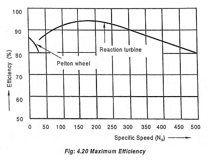
In impulse turbine due to its low specific speed, efficiency of the turbine is reduced because the large diameter of wheel which causes more bearing friction and windage losses. The value of specific speed (Ns) for higher efficiency is nearly 20.
Reaction turbine also gives less efficiency due to low specific speed. The larger diameter of wheel in low specific speed tends to friction losses. In addition to this leakage loss is more when comparing with leakage area through the clearance space and hydraulic friction comes in to notification due to small bracket passage. Due to low specific speed, these factors tend to reduce the efficiency.
In high speed reaction turbine, the friction and leakage losses are reduced with an increase in specific speed but the discharge losses increases rapidly. So the net effect of increase in specific speed tends to decrease the efficiency. Therefore it is preferable to select medium specific speed for reaction turbine and at constant load conditions.
The effect of specific speed on maximum efficiency is shown in Fig.4.20. High efficiency can be achieved by reaction turbine and impulse turbine. The maximum possible efficiency for impulse turbine is 82% but for reaction turbine is 90%.
The efficiency of pelton wheel does not decrease with its size and at the same time, pelton wheel is suggested for smaller power than reaction turbine.
(iv) Part load efficiency
Full load is defined as maximum efficiency of the turbine. If the load increases above full load, then it is called over load. If the load decreases below full load, then it is called part load.
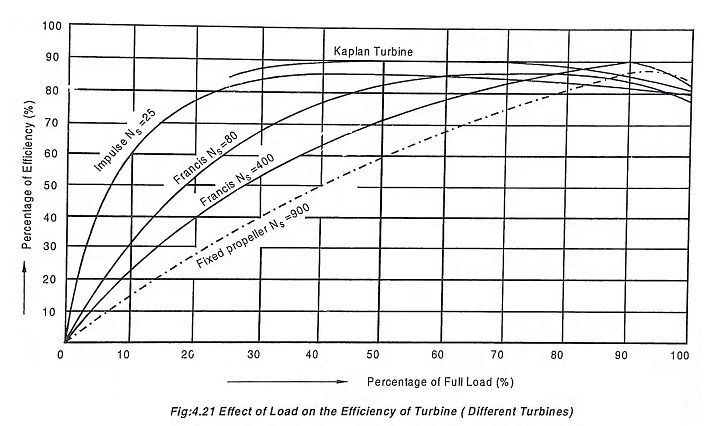
The part load efficiency for all type of turbine depends upon type of turbine and specific speed. The variations in part load efficiencies with different types of wheels are shown in Fig.4.21.
In pelton wheel, the flow of water through jet is reduced by governing mechanism, when the load on the turbine is reduced below full load. Therefore the part load curve is more flat in case of pelton turbine.
In reaction turbine, the water completely fills the bucket passage and rate of discharge is reduced [which is required at part load). Thus increases the discharge (or) and the velocity of water at outlet. Therefore, the efficiency decreases with decrease in load (part load) on the turbine.
(v) Heads
The choice of turbine depends upon function of power, speed and head of water available.
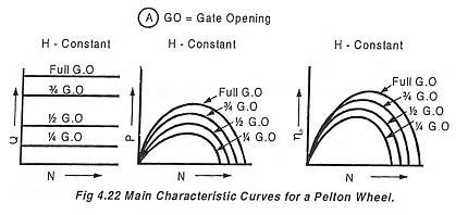
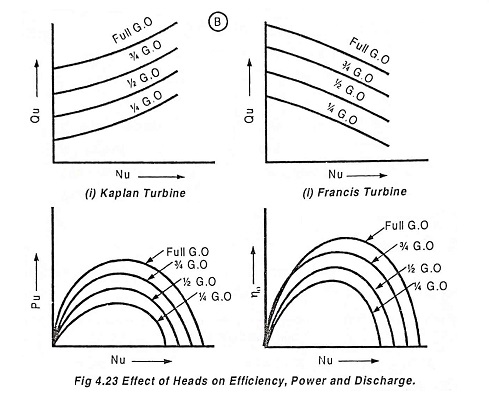
These curves are drawn by maintaining a constant head and a constant gate opening (G.O) on the turbine. By changing the load on the turbine, the speed is varied. For each speed (N), the corresponding values of power (P), discharge (Q) are noted and the overall efficiency (η0) is calculated. The unit power (Pu), unit discharge (Qu) and unit speed (Nu) are also calculated using these readings. Taking unit speed in the X-axis and the other values are taken in the Y-axis, various curves are plotted as shown in Fig.4.23. By changing the gate opening, the values of Qu, Pu and η0 are plotted. Fig.4.22 and Fig.4.23 show the effect of heads on efficiency, power and discharge for a Pelton wheel and reaction turbines [Francis and Kaplan] respectively.
| Sl. No. | Head of water in meters | Type of turbine |
| 1 | Above 300 m | Pelton turbine |
| 2 | 60 to 300 | Francis turbine |
| 3 | Below 60 | Kaplan (or) propeller turbine |
(vi) Types of water available
Water carrying dirt and sand is not suitable for reaction turbines at high head conditions which leads to erosion in runner blades and water is further restricted due to very small cross sectional area and easily becomes chocked due to floating debris which leads to high fluid friction losses.
The greater accessibility and simplicity of parts are required for replacement of parts due wear and tear (or) due to the chemical reaction of water.
(vii) Runaway speed
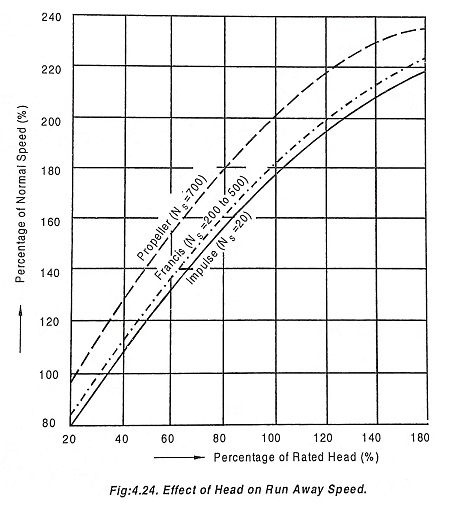
The speed of turbine increases with increase in head. Due to the increase in speed of turbine, the generator must be designed to stand the full runaway speed of turbines to which is connected to maximum head conditions. Due to higher runaway speed, the cost of machines increases.
The percentage runaway speed and percentage increase in power is shown in Fig.4.24.
(viii) Cavitation
When the specific speed of the turbine increases and crosses the recommended value leads to cavitation. The cavitation characteristics of the turbine is also to be considered since it affects the installation of a reaction turbine.
If cavitation occurs, it corrodes the runner blades with in a year’s operation. The dense material like steel and stainless steel resist better to cavitation than porous material like cast iron.
(xi) Number of units
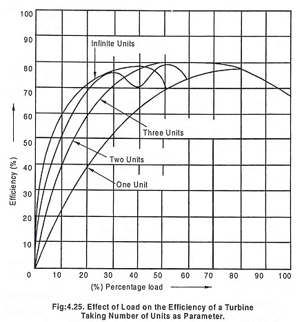
The overall efficiency of a large plants depend upon the number of units installed. A plant with two similar unit will have better average efficiency than one unit having the capacity of two unit. The plants containing three (or) more units would have still better average efficiency.
The effect of increase in number of units to same generation of power on efficiency is shown in Fig.4.25.
The Selection of Hydraulic Turbines of number of unit is management and economical problem, depends upon capital cost and running expense and it is not a design problem.
(x) Overall cost of the plant
The plant should be designed with minimum cost and also to give maximum efficiency (i.e, to generate power with minimum cost). The total cost includes capital cost and running cost.


