Series Capacitor – Working Principle, Phasor diaagram, Application:
In EHV and UHV transmission lines, series capacitor are connected in series with the line to reduce the effect of inductive reactance XL between the sending end and the receiving end of the line.
Voltage drop in the line is given as
![]()
without series capacitor
![]()
with series capacitor
where I is the current flowing through the line.
Thus with series capacitors in the line, the voltage drop ΔV in the line is reduced and the receiving-end voltage VR on load is improved.
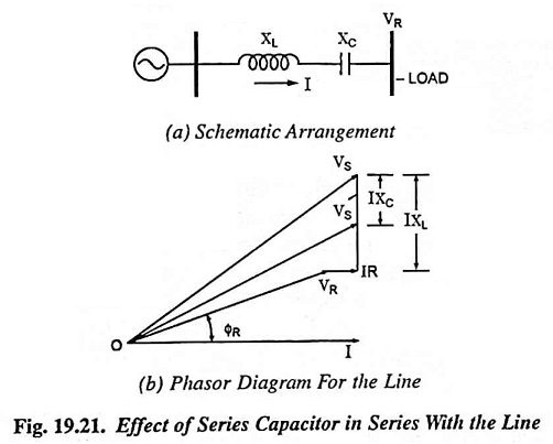
From phasor diagram shown in Fig. 19.21 (b), it is obvious that the voltage drop caused by an inductive load can be reduced particularly when the line has a large X/R ratio. In practice XC may be so chosen that the factor (XL – XC) sin ΦR becomes negative and numerically equal to R cos ΦR so that the voltage drop becomes zero. The ratio XC/XL expressed as a percentage is usually referred to as the percentage compensation.
Disadvantages:
One drawback of series capacitors is the high overvoltage produced across the capacitor terminals under short-circuit conditions. The drop across the capacitor under faulty conditions may be as large as 20 times that caused by full-load current under certain conditions. A spark gap with a high speed contactor is employed for the protection of capacitor under such conditions.
Applicatons:
Series capacitors are usually used for increasing the power transfer ability of the transmission line and not for voltage regulation.