AC Series Motor:
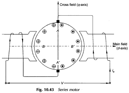
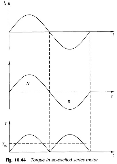
A series motor can be run from either dc or ac (single-phase) supply provided that both stator and rotor cores are laminated to limit the iron-loss. Figure 10.43 is the cross-sectional view of a AC Series Motor connected to ac supply. As the armature current alternates, the field polarity alternates in phase with it as shown in Fig. 10.44; as a consequence the torque developed (∞ Φia) is unidirectional with a pulsating component over and above the average value.
The pulsating component of torque is filtered out by the rotor and load inertia so that the speed pulsations are almost negligible. The necessity of laminating the stator (poles and yoke) is indicated by the alternating flux it is required to carry.
The current-carrying armature produces cross-flux along the q-axis in space quadrature with the main flux (in the d-axis). These two fluxes apart from being in space quadrature are alternating at a supply frequency. Each of these fluxes then induces rotational and static (transformer) emf’s in the armature.
Emf’s of Main Field (d-axis):
As in the dc case, rotational emf is induced in armature conductors adding to a maximum value at the q-axis brushes. The emf alternates in unison with flux/pole. The magnitude of this emf is maximum in coils BB’ (Fig. 19.43) and is zero in coils AA’ under the brushes. Hence, commutation remains unaffected by this emf.
Caused by time-variation of the flux/pole, transformer emf’s are induced in armature coils which add to net zero value at the brushes. These emfs have zero value in coils BB’ and maximum value in coils AA’. Since coils AA’ are shorted by the brushes, commutation is seriously affected resulting in brush sparking.
The rms value of the rotational emf caused by the main field is
where
- Φ = maximum value of flux/pole
This emf is in-phase with the main flux phasor.
Emf’s of Cross Field (q–axis Field):
The rotational emf caused by cross-flux (along q-axis) induces net zero emf at the brushes. This emf is zero in coils BB’ and maximum in coils AA’ thereby interfering in the commutation process.
On the other hand, the transformer emf of armature coils adds to a definite value and is alternating leading the cross flux by 90°. This emf is maximum in coils BB’ and zero in coils AA’ and so does not affect commutation.
The rms value of transformer emf Et at the brushes is calculated below:
where
- Np = turns/parallel path;
- Φa = armature (cross) flux; proportional to Ia
- Kb= space factor; though coil emf’s are in phase, their magnitude varies as cosine of angle the coil axis makes with the brush axis
Assuming the armature winding to be finely distributed, it can be easily shown that
Hence
The ratio of the transformer emf (Et) to the rotational emf (Ea) is
But
where
Circuit Model and AC Series Motor Phasor Diagram:
The net emf induced in the armature is the sum of the transformer emf and that due to leakage inductance (xa) and is given by
Since Et is caused by cross-flux whose origin is in armature current, the two must be in phase. Define
Thus the net inductive emf in the armature circuit is
where
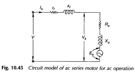
The circuit model of the AC Series Motor for ac operation can now be immediately drawn as in Fig. 10.45 where rf, xf = field resistance and reactance respectively.
From the circuit model of Fig. 10.45
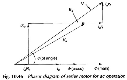
The corresponding phasor diagram is drawn in Fig. 10.46. The flux phasor Φ̅ (main) and Φ̅ (cross) are assumed in phase with motor current I̅a. In fact to be strictly correct I̅a will lead these flux phasors by a small angle on account of hysteresis and eddy-current losses of the motor.
Torque Developed:
As shown in the beginning, the torque developed is pulsating in nature with an average value and a predominant second harmonic component. The average torque is given by
Being a AC Series Motor Ea ∞ Ia (assuming linear magnetic circuit), the torque is therefore proportional to square of armature current which becomes directly proportional at high armature current because of saturation of the magnetic circuit.
Performance Characteristics of AC Series Motor:
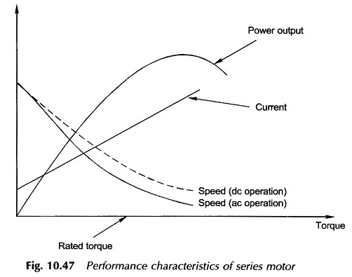
Figure 10.47 shows the performance characteristics of an AC Series Motor. The speed-torque characteristic has a typical series shape. The speed-torque characteristic for dc operation would lie somewhat higher as shown dotted. This is because of reactance voltage drops [Ia(xf + Xa)] in ac operation so that Ea and hence speed is lower for a given current and torque. The power factor of an ac operated AC Series Motor is rather poor because of the large series reactance (xf + Xa).
The no-load speed of a universal motor, unlike other machines, is very high (of the order of 20000 rpm). Therefore, the motor is smaller in size than other types for a given load. Universal motors are used where light weight is important, as in vacuum cleaners and portable tools which usually operate at high speeds (1500-15000 rpm).
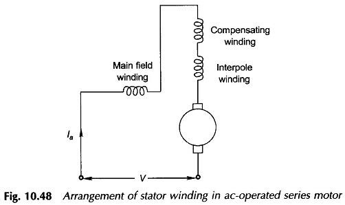
Compensating and Inter-pole Windings:
To improve the power factor of a AC Series Motor, the cross-flux which is mainly responsible for armature reactance must be cancelled out by a compensating winding connected in series with the armature circuit. The axis of this winding is along the brush axis and the winding must be spread over the full pole pitch for effective neutralization of cross-flux. Like in a dc machine the interpole winding when provided must be effective over a narrow interpolar region. The schematic connection diagram of all the stator windings and the armature is shown in Fig. 10.48.
