Short Circuit Current in Synchronous Generator:
The Short Circuit Current in Synchronous Generator being electrical in nature is much faster than the electromechanical dynamics discussed already. It will, therefore, be assumed that by the time the major features of the short-circuit phenomenon are over, the rotor speed remains constant at the synchronous value.
The Short Circuit Current in Synchronous Generator is a highly complex phenomenon as a number of coupled circuits are involved and further their self- and mutual-inductances are functions of the angle and therefore of time. The detailed mathematical model of this phenomenon is beyond the scope of this book. The treatment here will be qualitative based on physical reasoning.
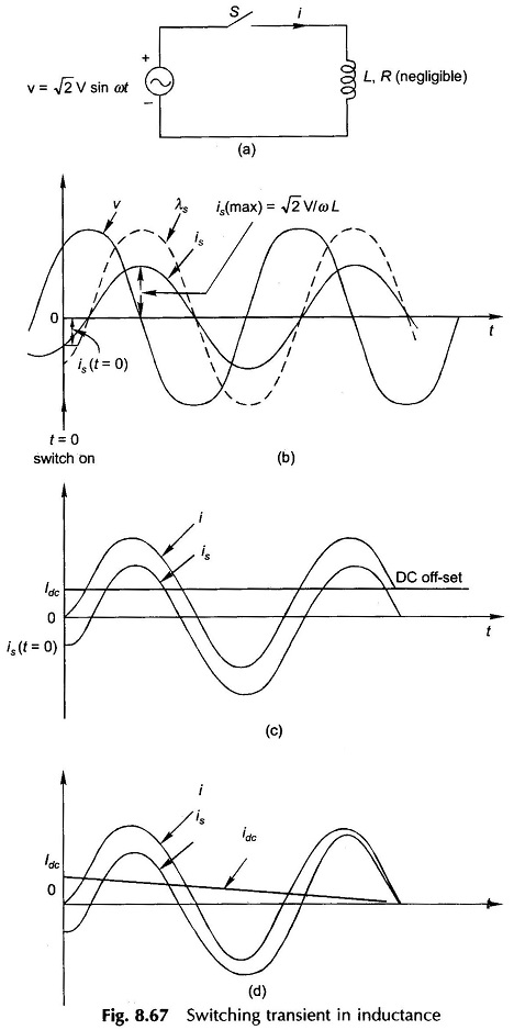
To understand the physical reasoning, which will be advanced soon, let us examine the physical picture of the transient phenomenon in an inductance switched onto a source of sinusoidal voltage as shown in Fig. 8.67(a). The resistance associated with the inductance is assumed to be negligible (as is the case in a synchronous machine) and would at the first instant be neglected. While a simple analytical approach would immediately give the quantitative answer to this problem, physical reasoning will however be followed. Figure 8.67(b) shows the waveforms of voltage, current and flux linkages in the circuit under steady-state conditions wherein the current and flux linkages lag the voltage by 90°. At the instant switch S is closed, the steady-state conditions demand that circuit current and associated flux linkages instantaneously acquire a specific value, is(t = 0). Since the flux linking the circuit has associated stored energy which cannot change instantaneously, the current and flux linkages must remain constant (at zero in the present case) at the instant of switching. This requires the appearance of a current Idc, called the dc off-set current in the circuit such that
The fact that the flux linkages of an inductive circuit cannot change instantaneously is known as the theorem of constant flux linkages. It greatly aids in determining the current Idc which must immediately flow in the circuit.
The maximum value of Idc occurs when the switch is closed at the instant where the is demanded is maximum which in the case of pure inductance is at the instant of voltage zero. Thus
If the circuit resistance is negligible, Idc remains constant. The net current in the circuit is
whose waveform is drawn in Fig. 8.67(c). Because of the presence of the dc off-set current
whose maximum possible value is
This is known as the current doubling effect.
If the small amount of resistance present is accounted for, the dc off-set current will decay as
when τ = R/L = circuit time-constant
The current waveforms in this case are drawn in Fig. 8.67(d). The net current finally settles to the steady-state current is after idc has died out (it will require time of the order of a few time-constants). The steady-state component of the net current is known as the symmetrical current, while the net current initially lacks symmetry due to the presence of the dc off-set current.
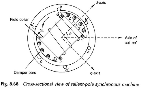
Now the problem of Short Circuit Current in Synchronous Generator whose cross-sectional view is shown in Fig. 8.68 will again be considered. The following assumptions will be made:
- Armature resistance is negligible.
- All the three phases are short-circuited simultaneously (symmetrical 3-phase short-circuit).
- Before the short-circuit, the machine is operating under no-load (open-circuit) condition.
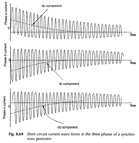
Since the flux linkages of each stator phase (caused by the direct-axis flux set up by the field current) cannot change instantaneously, dc off-set currents appear in all the three phases. These currents are proportional to the flux linkages of each phase at the instant of short-circuit, i.e. these are proportional to the cosine of the angle between the phase axis and d-axis. For example, if the d-axis is oriented along the a phase axis at the instant of short-circuit, the dc off-set current in phase a has a certain positive value while negative dc off-set currents of half this value would appear in phases b and c.
For short circuit at this instant the wave forms of short circuit currents in the three phases are shown in Fig. 8.69 which also indicates the dc off-set currents in dotted line.
If the dc off-set currents are removed from the Short Circuit Current in Synchronous Generator, we are left with the symmetrical short circuit current which is the same in all the three phases but for a phase difference of 120°.
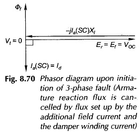
The symmetrical short-circuit current (in each phase) is 90° lagging current, constituting the d-axis current, the q-axis current being zero (see Fig. 8.70). It establishes a demagnetizing armature reaction along the d-axis. By the theorem of constant flux linkages the flux Φf linking the field winding and damper winding (in Fig. 8.68 damper bars form coils as 11′, 22′ and 33′ whose axis is along the d-axis) must be maintained by appearance of induced (unidirectional) currents on the field winding (over and above the normal excitation current) and damper winding. As a result the air-gap emf, Er initially equals Ef = VOC (no-load voltage). The short-circuit current is then (Er = Ef)/Xl, a very large value. The phasor diagram under these conditions is drawn in Fig. 8.70.
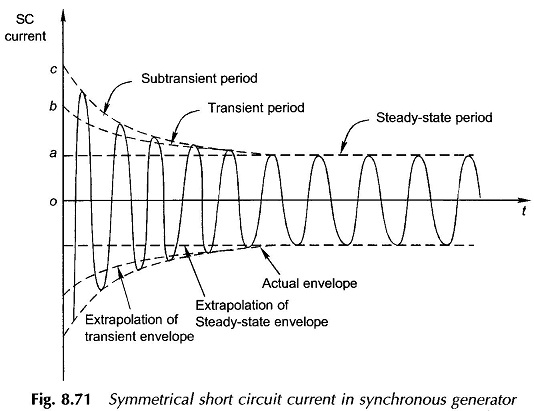
The induced currents in the damper and field windings decay at rates determined by their respective time-constants. The damper winding comprising a few thick bars has a much lower time-constant than that for the field winding and its induced current is the first to vanish. As the induced current of the damper winding decays, the net d-axis flux and therefore the air-gap emf (Er) reduces and the symmetrical short-circuit current decays accordingly as shown in Fig. 8.71. This initial period of decay of the short-circuit current is called the subtrasient period in which the current decay is governed mainly by the damper winding time-constant.
As time progresses the induced field current continues to decay governed by its own time-constant. As a consequence the net d-axis flux continues to decay and so does the symmetrical short-circuit current till the steady-state short-circuit current (Ef/Xd) is established after the induced current in the field winding has died out. This period of the short-circuit transient is called the transient period as indicated in Fig. 8.71
Figure 8.71 shows the complete waveform of the symmetrical Short Circuit Current in Synchronous Generator. This plot can be obtained from the oscillogram of the short-circuit current in one of the phases after the dc off-set value has been subtracted from it. The three periods—substransient, transient and steady-state—are indicated on the current envelope. The decaying envelope is clearly indicative of the fact that
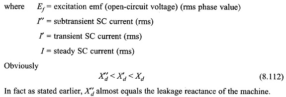
the equivalent d-axis reactance offered by the machine continuously increases as time progresses and finally settles to the steady value Xd when the armature reaction demagnetizing effect becomes fully effective. Extrapolation of the subtransient, transient and steady-state current envelopes identifies the ordinates Oa, Ob, and Oc on the current coordinate. The machine presents three different reactances, during the short circuit, as defined below: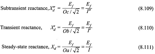
The variation of the rms SC current with time can be expressed as below following the physical arguments presented earlier
The effect of the dc off-set current on the symmetrical SC current can be accounted for by means of a suitable multiplying factor which depends upon the number of cycles that have elapsed after the short-circuit.
Certain Details:
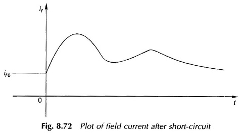
In the above physical picture certain finer points were purposely left out. The dc offset stator currents establish a fixed axis flux in air-gap which gradually decays. This flux induces fundamental frequency currents in the field and damper winding which contribute a d-axis oscillating field. This oscillating field can be split into two fields rotating at synchronous speed in opposite directions with respect to the rotor. One of these components is stationary with respect to the stator and reacts back on the dc off-set currents. The other component travels with respect to the stator at twice the synchronous speed and therefore induces the second harmonic in it.
The plot of the field current after the short-circuit on the stator exhibiting the dc and fundamental frequency transient current is shown in Fig. 8.72.
Short–Circuit under Loaded Conditions:
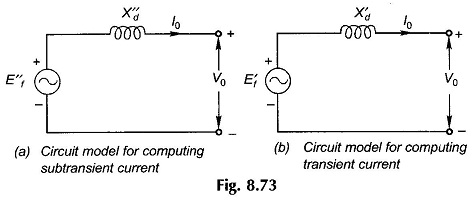
Short-circuit analysis of a loaded synchronous machine is quite involved and is beyond the scope of this book. The method of calculating short-circuit currents during the subtransient and transient periods will be presented here, without proof. The circuit models of the machine to be used in computing subtransient and transient currents are given in Figs 8.73(a) and (b) wherein in place of excitation emf, voltages behind subtransient and transient reactances are used. These are given as:
where V0 is the machine terminal voltage and I0 is the machine current prior to occurrence of the fault.
The subtransient and transient currents during short circuit are given by
Of course the steady-state Short Circuit Current in Synchronous Generator is given by
where Ef is the excitation emf and Xd, the steady-state d-axis reactance.

