What is Signal Generator?:
What is Signal Generator? : A signal generator is a vital component in a test setup, and in electronic troubleshooting and development, whether on a service bench or in a research laboratory. Signal generators have a variety of applications, such as checking the stage gain, frequency response, and alignment in receivers and in a wide range of other electronic equipment.
They provide a variety of waveforms for testing electronic circuits, usually at low powers. The term oscillator is used to describe an instrument that provides only a sinusoidal output signal, and the term generator to describe an instrument that provides several output waveforms, including sine wave, square wave, triangular wave and pulse trains, as well as an amplitude modulated waveform. Hence, when we say that the oscillator generates a signal, it is important to note that no energy is created; it is simply converted from a dc source into ac energy at some specific frequency.
There are various types of signal generator but several requirements are common to all types.
- The frequency of the signal should be known and stable.
- The amplitude should be controllable from very small to relatively large
- Finally, the signal should be distortion-free
The above mentioned requirements vary for special generators, such as function generators, pulse, and sweep generators.
Various kinds of signals, at both audio and radio frequencies, are required at various times in an instrumentation system. In most cases a particular signal required by the instrument is internally generated by a self-contained oscillator. The oscillator circuit commonly appears in a fixed frequency form (e.g. when it provides a 1000 c/s excitation source for an ac bridge). In other cases, such as in a Q-meter, oscillators in the form of a variable frequency arrangement for covering Q-measurements over a wide range of frequencies, from a few 100 kHz to the MHz range, are used.
In contrast with self-contained oscillators that generate only the specific signals required by the instrument, the class of generators that are available as separate instruments to provide signals for general test purposes are usually designated as signal generators. These AF and RF generators are designed to provide extensive and continuous coverage over as wide a range of frequencies as is practical.
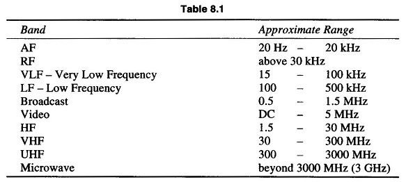
In RF signal generators, additional provision is generally made to modulate the continuous wave signal to provide a modulated RF signal. The frequency band limits are listed in Table 8.1.
Most of the service type AF generators commonly cover from 20 Hz to 200 kHz, which is far beyond the AF range.
In more advanced laboratory types of AF generators, the frequency range extends quite a bit further e.g. a Hewlett Packard model covers 5 Hz – 600 kHz and a Marconi model generates both sine and square waves and has a very wide range of 10 Hz – 10 MHz.
Fixed Frequency AF Oscillator:
In many cases, a self-contained oscillator circuit is an integral part of the instrument circuitry and is used to generate a signal at some specified audio frequency. Such a fixed frequency might be a 400 Hz signal used for audio testing or a 1000 Hz signal for exciting a bridge circuit.
Oscillations at specified audio frequencies are easily generated by the use of an iron core transformer to obtain positive feedback through inductive coupling between the primary and secondary windings.
Variable AF Oscillator:
A variable AF oscillator for general purpose use in a laboratory should cover at least the full range of audibility (20 Hz to 20 kHz) and should have a fairly constant pure sinusoidal wave output over the entire frequency range.
Hence, variable frequency AF generators for laboratory use are of the RC feedback oscillator type or Beat Frequency Oscillator (BFO) type.
Basic Standard Signal Generator (sine Wave):
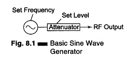
The sine wave generator represents the largest single category of signal generator. This instrument covers a frequency range from a few Hertz to many Giga-Hertz. The sine wave generator in its simplest form is given in Fig. 8.1.
The simple sine wave generator consists of two basic blocks, an oscillator and an attenuator. The performance of the generator depends on the success of these two main parts. The accuracy of the frequency, stability, and freedom from distortion depend on the design of the oscillator, while the amplitude depends on the design of the attenuator.

