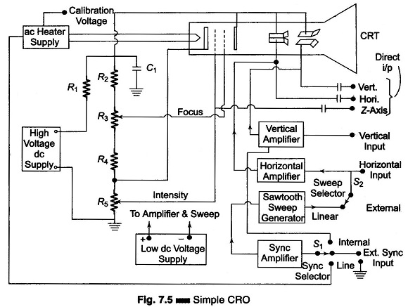
Block Diagram of CRO:
The Basic Block Diagram of CRO is shown in Fig.7.5. The ac filament supplies power to the CRT heaters in the Block Diagram of CRO. This also provides as accurate ac calibrating voltage. CRT dc voltage is obtained from the HV dc supply through voltage dividers. R1 – R5 Included along with this voltage divider is a potentiometer (R3) which varies the potential at the focusing electrode, known as focus control, and one which varies the control grid voltage, called the intensity control (R5).
Capacitor C1 is used to ground the deflection plates and the second anode for the signal voltage, but dc isolates these electrodes from the ground.
Normally S2 is set to its linear position. This connects the sweep generator output to the horizontal input. The sweep voltage is amplified before being applied to the horizontal deflecting plates.
When an externally generated sweep is desired, S2 is connected to its external position and the external generator is connected to the input. The sweep synchronizing voltage is applied to the internal sweep generator through switch S1, which selects the type of synchronization.
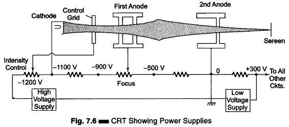
CRT Showing Power Supply:
Figure 7.6 shows the various voltages applied to CRT electrodes. The intensity control controls the number of electrons by varying the control grid voltage. Focusing can be done either electrostatic-ally or electromagnetically. Electrostatic focusing is obtained by using a cylindrical anode, which changes the electrostatic lines of force which controls the beam.

