Single Phase Half Controlled Rectifier Control of DC Separately Excited Motor:
Single Phase Half Controlled Rectifier Control is shown in Fig. 5.29(a). In a cycle of source voltage defined by Eq. (5.71), T1 receives gate pulse from α to π and T2 from (π+ α) to 2π. Motor terminal voltage and current waveforms for the dominant discontinuous and continuous conduction mode are shown in Figs. 5.29(b) and (c) respectively.
In discontinuous conduction mode, when T1 is fired at α, motor gets connected to the source through T1 and D1 and va = vs. The armature current flows and D2 gets forward biased at π. Consequently, armature current freewheels through the path formed by D1 and D2, and the motor terminal voltage is zero. Conduction of D2 reverse biases T1 and turns it off. Armature current drops to 0 at β and stays zero until T2 is fired at (π+ α). Similarly, the continuous conduction mode can be explained.
Discontinuous Conduction:
A cycle of motor terminal voltage consists of three intervals (Fig. 5.29(b)):
- Duty interval (α ≤ ωt ≤ π): Armature current is given by Eq. (5.77). Substitution of ωt = π in this equation gives ia(π).
- Freewheeling interval (π ≤ ωt ≤ β): Operation is governed by the following equation:
Solution of (5.87) subject to ia(π) as the initial current yields
- Zero current interval (β ≤ ωt ≤ π + α): Equation (5.73) is applicable. Since ia(β) = 0, one gets from (5.88)
β can be calculated by the solution of Eq. (5.89). Now
From Eqs. (5.7), (5.8), (5.79) and (5.90)
Boundary between continuous and discontinuous conduction is reached when β = π + α. Substituting β = π + α in (5.89) gives the critical speed ωmc, which separates continuous conduction from discontinuous conduction for a given a.
Continuous Conduction:
From Fig. 5.29(c)
From Eqs. (5.7), (5.8), (5.79) and (5.93)
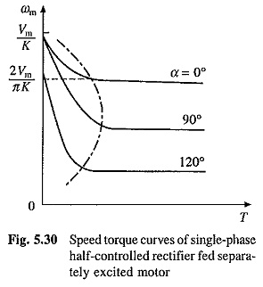
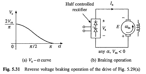
Speed-torque curves are shown in Fig. 5.30. No load speeds are given by Eqs. (5.85) and (5.86). Operation of drive, which operates in quadrant I only, is represented by equivalent circuit of Fig. 5.28(b). It is useful to note why the drive should not be operated in quadrant IV. Figure 5.31(a) shows plot of Va with α (Eq. (5.93)) for Single Phase Half Controlled Rectifier Control for continuous conduction operation. The output voltage cannot be reversed. When coupled to an active load, in the motor speed can reverse, reversing E as shown in Fig. 5.31(b). As current direction does not change, machine now works as a generator producing braking torque. Since, rectifier voltage cannot reverse, generated energy cannot be transferred to ac source, and therefore, it is absorbed in the armature circuit resistance. Braking so obtained is nothing but the reverse voltage braking (plugging). Such a braking is not only inefficient, but also causes a large current [Ia = (Va + E)/Ra] to flow through the rectifier and motor. Since it cannot be regulated by adjustment of firing angle, it will damage the rectifier and motor. Therefore, when load is active, care should be taken to avoid such a operation. If such a operation cannot be avoided, fully-controlled rectifier should be used.
A Single Phase Half Controlled Rectifier Control is cheaper and gives higher power factor compared to single-phase fully-controlled rectifier. But then it only provides control in quadrant I.


