Single Sideband Modulation (SSB):
Single Sideband Modulation (SSB) can he obtained by passing the output of a carrier suppressor (product modulator) through filter circuits that are selective to transmit one sideband while suppressing the other. However, this method is suitable only for obtaining Single Sideband Modulation corresponding to low or moderate carrier frequencies. The other method is the phase shift method which avoids filter and instead uses two balanced modulators and two phase shifting networks. These two methods are described as below:
Frequency Discrimination Method:
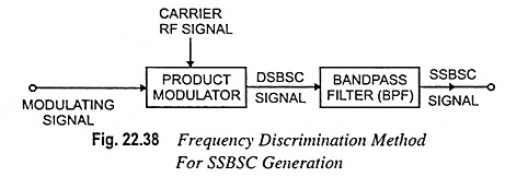
In a frequency discrimination method, firstly, a DSBSC signal is generated simply by using an ordinary product modulator or a balanced modulator. After this, from the DSBSC signal one of the two sidebands is filtered out by a suitable bandpass filter. The schematic diagram for this method is depicted in Fig. 22.38.
In fact, the design of bandpass filter is quite critical and thus puts some limitations on the modulating or baseband and carrier frequencies. The frequency discrimination method for SSBSC generation have got following limitations.
- This method is useful only if the baseband signal is restricted at its lower edge due to which the upper and lower sidebands are non-overlapping. For example, the filter method is used for speech communication where lowest spectral component is 70 Hz and it may be taken as 300 Hz without affecting the intelligibility of the speech signal. However, this system is not useful for video communication where the baseband signal starts from dc (0 Hz).
- The another restriction of this method is that the baseband signal must be appropriately related to the carrier frequency. In fact, the design of the bandpass filter (BPF) becomes difficult if the carrier frequency is quite higher than the bandwidth (BW) of the baseband signal.
Phase Shift Method of Single Sideband Modulation SC Generation:
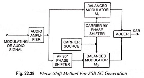
This method uses two balanced modulators and two phase shifting networks as shown in Fig. 22.39. This method avoids the use of filters. In Fig. 22.39, one of the modulators M1 receives the carrier voltage shifted by 90° and the modulating voltage, whereas another balanced modulator M2 receives the modulating voltage shifted by 90° and carrier voltage. Both balanced modulators give an output consisting only of sidebands.
Both the upper sidebands lead the input carrier voltage by 90°. One of the lower sideband leads the reference voltage by 90° and the other lags behind it by 90°. The two lower sidebands are thus out of phase, and when combined together in the adder, they cancel each other. The upper sidebands are in phase at the adder and therefore, they add producing Single Sideband Modulation in which the lower sideband has been cancelled.
Mathematical Analysis: Let the expressions for modulating signal and carrier signal be sin ωmt and sin ωct respectively.
Now the balanced modulator M1 will receive sin ωmt and sin (ωct + 90°) and modulator M2 will receive sin (ωmt + 90°) and sin ωct.
We know that the output of balanced modulator M1 will contain sum and difference frequencies
Hence
Similarly, the output of balanced modulator M2 will contain
Thus, the output of adder will be
The extent of SB suppression depends upon (i) balancing capacity of the modulator (ii) control accuracy of the 90° phase of the carrier waves and (iii) error in maintenance of 90° shift between the two modulating waves.
Advantages:
The phase shift method was introduced to overcome the bulk of filter system using L-C filters. This method has the advantages of (i) ease of switching from one SB to another (ii) ability of generating Single Sideband Modulation at any frequency and (iii) use of low audio frequencies for modulation.
Disadvantages:
In case the phase shifter provides a phase change other than 90° at any audio frequency then that particular frequency will not be completely removed from the unwanted SB. Also, in case the two modulators are not identical, cancellation will not be complete.


