Sinusoidal Response of RLC Circuit:
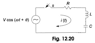
Consider a Sinusoidal Response of RLC Circuit consisting of resistance, inductance and capacitance in series as shown in Fig. 12.20.
Switch S is closed at t = 0. At t= 0, a sinusoidal voltage V cos (ωt + θ) is applied to the RLC series circuit, where V is the amplitude of the wave and θ is the phase angle. Application of Kirchhoff s voltage law to the Sinusoidal Response of RLC Circuit results in the following differential equation.
Differentiating the above equation, we get
The particular solution can be obtained by using undetermined coefficients. By assuming
Substituting ip, i′p and i″p in Eq. 12.33, we have
Comparing both sides, we have
Sine coefficients.
Cosine coefficients
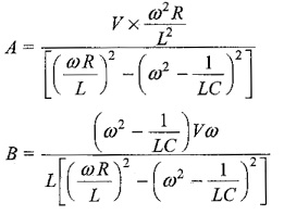
Solving Eqs 12.38 and 12.39, we get
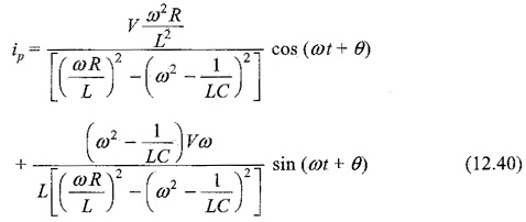
Substituting the values of A and B in Eq. 12.34, we get
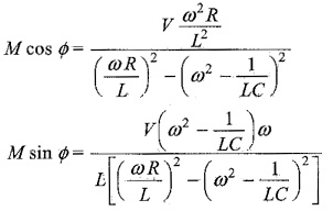
Putting
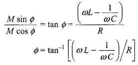
To find M and Φ we divide one equation by the other
Squaring both equations and adding, we get
The particular current becomes
The complementary function is similar to that of DC series RLC circuit. To find out the complementary function, we have the characteristic equation
The roots of Eq. 12.42, are
By assuming
K2 becomes positive, when (R/2L)2 > 1/LC
The roots are real and unequal, which gives an overdamped response. Then Eq. 12.42 becomes
The complementary function for the above equation is
ic = c1 e(K1 + K2)t + c2 e(K1 – K2)t
Therefore, the complete solution is
i = ic + ip
K2 becomes negative, when (R/2L)2 < 1/LC
Then the roots are complex conjugate, which gives an underdamped response. Equation 12.42 becomes
[D – (K1 + jK2)] [D – (K1 – jK2)]i = 0
The solution for the above equation is
ic = eK1t [c1 cos K2t + c2 sin K2t]
Therefore, the complete solution is
i = eK1t [c1 cos K2t + c2 sin K2t]
K2 becomes zero, when (R/2L)2 = 1/LC
Then the roots are equal which gives critically damped response. Then, Eq. 12.42 becomes (D – K1) (D – K1) i = 0.
The complementary function for the above equation is
ic = eK1t (c1 + c2t)
Therefore, the complete solution is
i = ic + ip
i = eK1t (c1 + c2t)
