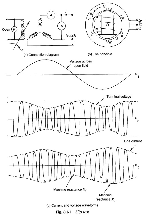
Slip Test on Synchronous Machine:
Direct and quadrature axis reactances of a salient-pole synchronous machine can be estimated by means of a test known as the Slip Test on Synchronous Machine. The machine armature is connected to a 3-phase supply whose voltage is much less than the rated voltage of the machine, while the rotor is run at speed close to synchronous with the field winding left open-circuited (unexcited) as shown in Fig. 8.61(a). Since the excitation emf is zero, heavy currents would be drawn by the armature if connected to the rated voltage supply.
The currents drawn by the armature set up an mmf wave rotating at synchronous speed as shown in Fig. 8.61(b). Since the rotor is being run at a speed close to synchronous, the stator mmf moves slowly past the field poles at slip speed (ns~n). When the stator mmf is aligned with the d-axis (field poles), flux Φd/pole is set up so that effective reactance offered by the machine is Xd. Similarly when the stator mmf aligns with the q-axis, the flux set up is Φd/pole and the machine reactance is Xq. The current drawn by the armature therefore varies cyclically at twice the slip frequency as shown by the current waveform drawn in Fig. 8.61(c)—the rms current is minimum when machine reactance is Xd and is maximum when it is Xq. Because of cyclic current variations and consequent voltage drop in the impedance of supply lines (behind the mains), the voltage at machine terminals also varies cyclically and has a minimum value at maximum current and maximum value at minimum current as shown by the voltage waveform of Fig. 8.61(c).
The machine reactances can be found as
The phenomenon of armature current going through maximum and minimum values during the Slip Test on Synchronous Machine is also easily seen from Eqs. (8.86) and (8.87) with Ef = 0
At δ = 0° (air-gap field axis oriented along d-axis),
and at δ = 90° (air-gap field axis oriented along q-axis)
Of course during the Slip Test on Synchronous Machine Vb = Vt (line/√3).
Observation of the voltage induced in the field during the Slip Test on Synchronous Machine is helpful in location of maxima/minima on current and voltage wave shapes. As the flux set up by armature currents moves past the rotor field, the flux linkage of the field vary and an emf of twice the slip frequency is induced in it. When the rotor field is aligned with the armature mmf, its flux linkages are maximum while the rate of change of flux linkage is zero, i.e. the voltage across the open field goes through zero at this instant which identifies Xd of the machine. It similarly follows that Xq is identified with the voltage maximum in the field. The wave of voltage across the open-field with reference to current and voltage waves at the armature is also shown in Fig. 8.61(c).
Since current and voltage meters as connected in Fig. 8.61(a) would oscillate at twice the slip frequency, the slip must be kept very small so that dynamics of the meters do not introduce errors in reading maximum/minimum values. Greater accuracy is achieved by using a recording oscillogram.

