Speed Control of DC Motor using Feedback Loop:
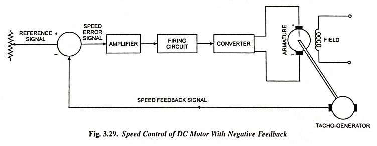
An open-loop system can be converted into a closed-loop system by employing a speed control of dc motor using feedback loop, as illustrated in Fig. 3.29. The tacho-generator is a permanent magnet dc generator whose output emf is directly proportional to the speed. The difference of input speed setting and speed feedback provides the error signal. The error signal is amplified by the amplifier and supplied to the firing circuit of the converter. Thus the firing of converter thyristors is advanced or delayed depending on whether the actual speed is less than or more than the desired speed.
Let the desired speed of motor be 1,200 rpm, error signal be 0.1 V, converter output be 240 V and output of tacho-generator be 10 V per 1,000 rpm. If the input setting is 12.1 V, the converter output will be 240 V and motor speed will be 1,200 rpm. If the load torque causes the decrease in speed and let the speed become 1,190 rpm, the output of tacho-generator will be 11.9 V increasing the error signal to 0.2 V. The converter output voltage will increase causing the speed to increase to 1,200 rpm. If the speed tends to increase beyond 1,200 rpm, the error signal will become less than 0.1 V and the output voltage of the converter will decrease, thus reducing the motor speed. Thus negative feedback is employed for control of motor speed.
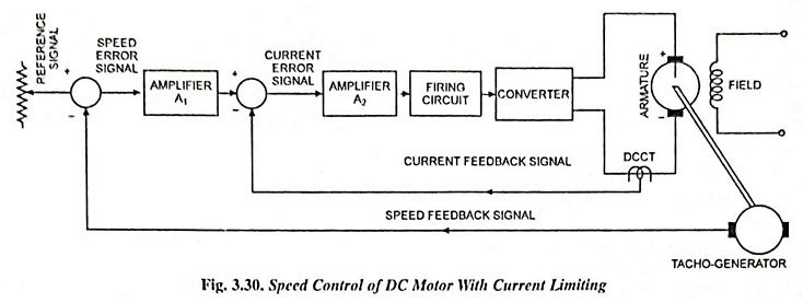
A change in motor speed causes a temporary increase in motor and thyristor currents. Excessive current, however, can be avoided by an automatic current limiting circuit using another feedback loop, as shown in Fig. 3.30. The dc current transformer (dc CT), measures the converter output current and develops a voltage proportional to current. This signal is fed back, as illustrated at a position between the two amplifiers. If the converter current tends to increase, the output of dc CT increases thus reducing the current error. Thus the output current of the converter is reduced to the safe value.

