Speed Control of Three Phase Induction Motor:
The problem of speed control of three phase induction motor in particular is of great practical importance. In a number of industries motors must satisfy very strict speed characteristic requirements, both with respect to the range and smoothness of control and also with respect to economical operation. From the view point of speed control of three phase induction motor characteristics, induction motors are inferior to dc motors. The speed of a dc shunt motor can be adjusted between wide range with good efficiency and speed regulation, but in induction motors speed cannot be varied without loosing efficiency and good speed regulation.
The speed of an induction motor is given by the expression
Thus there are three factors viz, supply frequency f, number of poles P and slip s on which the speed of an induction motor depends. Hence to change the speed of an induction motor it is essential to change at least one of the above three factors.
Methods of speed control of three phase induction motor are distinguished according to the main action on the motor : (i) from the stator side, and (ii) from the rotor side.
Various methods of speed control of three phase induction motor from stator side are (a) variation of supply frequency (b) variation of applied voltage and (c) by changing the number of poles. From the rotor side the speed may be controlled (a) by changing the resistance in the rotor circuit and (b) by introducing into the rotor circuit an additional emf of the same frequency as the fundamental emf of the rotor.
For the latter method of speed control of three phase induction motor, an additional electrical machine or several such machines are required. A set consisting of a regulated induction motor and one or more additional electrical machines connected to it electrically or mechanically is called cascade. Commutator machines are commonly used as the additional machines.
1. Speed Control By Variation of Supply Frequency
This method of speed control of three phase induction motor provides wide speed-control range with gradual variation of the speed throughout this range. The major difficulty with this method is how to get the variable frequency supply. The auxiliary equipment required for this purpose results in a high first cost, increased maintenance and lowering of the overall efficiency. That is why, this method is not employed for general-purpose speed control applications. Inspite of the fact that this scheme is complicated, there are certain applications in which its wide, continuously variable, speed range and good speed regulation makes its use highly desirable.
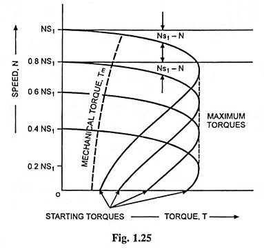
If an induction motor is to be operated at different frequencies with practically constant values of efficiency, power factor, overload capacity and a constant absolute slip, then, with the iron unsaturated, it is essential that the supply voltage be varied in proportion to supply frequency.
This kind of variation can occur for example, if the supply generator is subjected to the speed variations, either due to momentary overloads or because of a noticeable speed regulation. Both output voltage and frequency vary as the speed if no automatic correction is provided. On some large marine drives, the propeller motors are induction type and are speed controlled from such a local supply which is provided by synchronous generators coupled to variable speed turbines. Even in such cases the range of speed variation is limited, because the efficiency of the prime movers falls rapidly with the change in speed from that for what they are designed.
Typical speed-torque curves for four different frequencies are shown in Fig. 1.25.
2. Speed Control by Variation of Supply Voltage
This is a slip-control method with constant frequency variable supply voltage. In this method of speed control of induction motors, the voltage applied to the stator is varied for varying the speed.
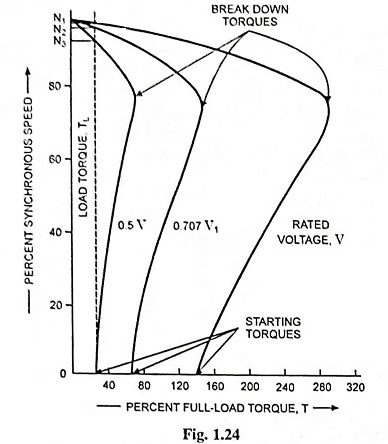
This method of speed control of three phase induction motor is simple, low in first cost and has low maintenance cost but it has limited use because (i) the operation at voltages exceeding rated voltage is restricted by magnetic saturation, (ii) a large change in voltage is required for a relatively small change in speed (iii) the developed torque reduces greatly with the reduction in supply voltage and the motor will come to standstill if the load torque exceeds the pull-out torque of the motor corresponding to reduced supply voltage and (iv) the range of speed control is very limited in the downward direction i.e., from rated speed to lower speeds.
In general, this method of speed control of three phase induction motor is used only on loads where the torque required drops off considerably as the speed is reduced such as with small squirrel cage motors driving fans.
The variable voltage may be obtained by means of either saturable reactors, variac, or tap-changing transformers.
The speed-torque characteristics with reduced voltages are illustrated in Fig. 1.24.
3. Speed Control By Changing the Number of Poles
This method is easily applicable to squirrel cage motors because a cage winding automatically reacts to create the same number of poles as the stator. This method of speed control of three phase induction motor is generally not practicable with wound rotor motors as in such machines this method would involve considerable complications of design and switching, since the interconnections of both primary and secondary would have to be changed simultaneously in a manner to produce the same number of poles in both windings. Otherwise, negative torque will be developed by certain of the rotor conductor belts.
The number of pole pairs in the stator can be changed as follows :
(a) By Using Multiple Stator Windings: In this method of speed control of three phase induction motor, two or more completely independent windings, each wound for different number of poles, are placed in the same stator slots. The number of stator winding poles are in this
case in no way interrelated and can be arbitrarily chosen depending on the operating conditions of this motor. For example, a two speed motor may have two stator windings, one wound for 4 poles and another for 6 poles which will give synchronous speeds of 1,500 rpm and 1,000 rpm with a supply frequency of 50 Hz. Motors with four independent stator windings are also used sometimes and they give four different synchronous (and hence running) speeds. Of course, one winding is used at a time, the others being entirely inoperative. Change-over from one speed to the another may be done by a mechanical switch or by contactors. With such an arrangement, the winding or windings which is/are not being used must be kept open circuited by the switch, or at least left in star. Otherwise, because of transformer action, the winding which is connected to the supply would induce voltages in the idle winding(s) and cause overheating due to the subsequent circulating currents.
The regulation itself amounts to changing the motor speed in steps as one or another stator winding is connected to the supply mains. At each change, the motor finds itself under conditions essentially analogous to the starting conditions, i.e., a large current and reduced torque. Because of inactive conductors, this method of pole changing requires a large stator than a single-speed motor of the same rating. This method has been used for elevator motors, traction motors and also for small motors driving machine tools.
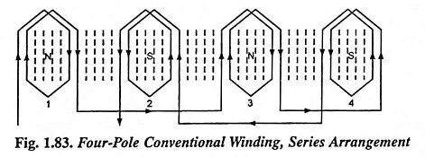
(b) Consequent Pole Method: The method of pole changing for speed control of three phase induction motor described above in (a) i.e., multiple stator winding method, is employed only in small motors. In large motors, it is more expedient to employ consequent pole technique which eliminates the necessity of having multiple stator windings for changing the number of stator poles. This method of speed control of three phase induction motor makes use of the entire winding for each speed. Normally, for a single speed motor, successive coil groups are wound so as to create poles of opposite polarity in succession. This is illustrated in Fig. 1.83, where one phase of a four-pole winding is developed.
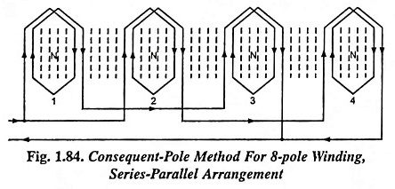
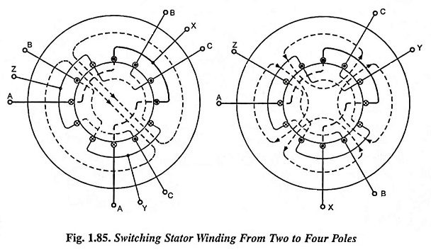
It should be noted that all the coils are in series but that the end connections are made to alternate groups, i.e., group 1 to group 3, and group 4 to group 2. Now the end connections of the groups, with the same coils, can be changed so as to have successive coils of the same polarity, as illustrated in Fig. 1.84. By paralleling the series connections of groups 2-4 with that groups 1-3, the polarity of group 2 and 4 has changed, so that there are now four successive north poles. As a consequence of this south poles are created between each of the north poles, and the motor now has an 8-pole winding. Thus for a 50 Hz supply, the series arrangement gives a synchronous speed of 1,500 rpm while the series-parallel arrangement gives a synchronous speed of 750 rpm. It is also possible to use a series parallel arrangement for the 4-pole winding and then switch to the series arrangement for 8-pole winding. A circuit for switching a three phase winding from 2 to 4 pole winding is shown in Fig. 1.85.
By reconnecting all the coil groups for the same polarity, the stator acts as though it has twice as many poles as pole groups. The additional poles so created are called the consequent poles, and the winding is known as a consequent pole winding. By an unique switching arrangement, it is possible to have the standard (or conventional) connection on one side of a double-throw switch and the consequent pole connection on the other side of the switch. Thus two speeds can be obtained, the higher speed with the conventional connection and half speed with consequent-pole connection.
In the motors using consequent-pole technique for speed control, the best possible design is not usually obtainable at both speeds. That is, desirable characteristics, such as high power factor, are sacrificed at one speed in order that a reasonably good power factor be obtained at the other speed. Sometimes the stator connections are changed from delta to star at the same time that the pole connections are changed. This changes the voltage and makes possible a better motor at each speed.
Two-speed motors are usually made with one winding on the stator, the number of poles being changed in the ratio 1:2. Three- and four-speed motors are provided with two windings on the stators, one or both of which are made with changing the number of poles. For example if it is desired to obtain a motor for four synchronous speeds; 1500, 1,000, 750 and 500 rpm, two windings should be placed on the stator, one of which giving 4 and 8 poles and the other giving 6 and 12 poles.
Employing a series-parallel connection of phase groups of individual phases, the phases can themselves be connected in star/delta resulting in two-speed operation with the three types of torque-speed characteristics viz constant torque, constant power output and variable torque.
Owing to complications in the design and switching of interconnection of the stator windings, it is not feasible to obtain more than four speeds for any motor through this method of speed control. This method also does not provide gradual speed control. That is why, this method is not employed for general-purpose speed control applications. However, this method is very satisfactory for applications, such as ventilating fans, conveyors, machine tools, or other applications which require operation at only two or four approximately constant speeds which it will provide. This method has the advantage of simplicity, good speed regulation for each setting, high efficiency and moderate initial cost and maintenance.
The number of pole pairs on the stator can also be changed by using pole amplitude modulation technique-a suppressed-carrier modulation technique. This method of pole changing has the advantage that the ratio of the two speeds obtainable need not be necessarily 2:1 as in the consequent pole method.
4. Stator Impedance Control
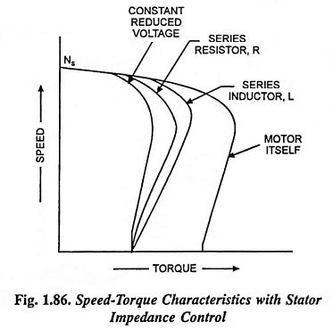
Reduced voltage at the machine terminals can be had by inserting balanced resistors or inductors in series with each stator lead. Under such conditions, the motor terminal voltage becomes dependent on motor current and the voltage changes with the acceleration of motor. Typical-speed torque characteristics are illustrated in Fig. 1.86.
If impedance (R or X) is adjusted so as to provide the same starting torque, the speed-torque characteristic in case of addition of inductor would have larger torque than with additional resistance. Besides, both of these characteristics enable us to have torques larger than that obtainable with the characteristic with reduced applied voltage, for same starting torque. Insertion of resistor in the stator circuit improves the power factor, but at the cost of greater energy losses.
5. Speed Control by Variation of Rotor Resistance (or Rotor Resistance Control)
Wound rotor motors are usually started by connecting starting resistances in the secondary circuit, which are shorted out in steps as the motor speeds up. If the ohmic values of these resistances are properly chosen and if these resistances are designed for continuous operation, they can serve dual purpose, starting and speed control. As obvious this method can be applied to wound rotor motors alone. Smoothness of speed control depends upon the number of steps of resistances that are available. Control is provided in the direction downward from the base speed. The range of speed control is not constant and depends on the value of the load. This method of speed-control has characteristics similar to those of dc shunt motor speed control by means of resistance in series with the armature. Its main disadvantages are lower efficiency and poor speed regulation due to increase in rotor resistance at low-speed settings. For instance, at 50 per cent of synchronous speed the efficiency of rotor is only 50 per cent and the efficiency of the motor would be somewhat less. The speed variation is limited to a range of 50-100% only. Liquid rheostats are preferred over metallic rheostats as they have no inductance and the resistances can be cut out smoothly giving a uniform torque.
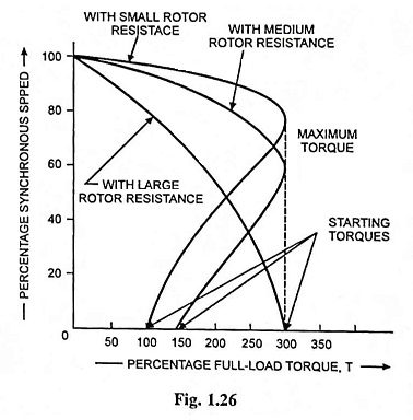
The introduction of external resistors in the rotor circuit of a slip-ring induction motor will modify the speed-torque characteristics as illustrated in Fig. 1.26.
This method of speed control of three phase induction motor as such is, therefore, not suitable for controlling speed at constant torque. But this method is widely used for loads where the torque required drops off considerably as the speed is reduced such as fan loads for which the power input drops noticeably as the speed is reduced which in turn reduces the rotor copper losses. Moreover, this method is not adopted for continuous speed control but is preferred for intermittent (short time) operation. Such a method of speed control is widely used in practice, for low-power motors and in overhead cranes. It is sometimes used however, for speed regulation of rolling mills especially where they are provided with flywheels for reducing the load peaks in the circuit. Here the rheostat, called the speed regulator, is automatically switched on when the load increases, and as a result speed decreases and part of the load is compensated at the expense of kinetic energy of the flywheel. Conversely, when the load decreases, the rotor circuit resistance is reduced; the speed increases and the flywheel begins to store kinetic energy.
6. Secondary Foreign Voltage Control
In this method, the speed of an induction motor is controlled by injecting a voltage of slip frequency in the secondary circuit. If injected voltage is in phase with the induced emf in the secondary circuit, it is equivalent to decreasing of resistance in the secondary circuit, therefore, slip decreases or speed increases. It is possible to achieve super-synchronous speeds by injecting a voltage of slip frequency in phase with the induced cmf in the rotor circuit. If injected voltage is in phase opposition to the induced emf in the secondary circuit, it is equivalent to increasing of resistance in the secondary circuit, hence resulting in increase in slip or reduction in speed. Thus a large range of speed control is possible by this method by including frequency-converting equipment in the rotor circuit.
In this method the disadvantages of lower efficiency and poor speed regulation are overcome, but, since it requires one and usually more auxiliary machines to inject emf of slip frequency in the secondary circuit, therefore, it is costlier and used with motors of very large rating, such as for motors in steel mills.
Several methods have been developed to control speed of induction motors by injecting a voltage of slip frequency in the secondary circuit. The different methods vary in their requirements for auxiliary equipment; from the incorporation of the auxiliary equipment in the design of induction motor itself to a fairly complicated system of auxiliary rotating machines and adjustable ratio transformers. The basic creteria that such a system must fulfill are : (i) that the variable foreign voltage have a slip frequency, i.e., frequency equal to sf and (ii) that the energy associated with the foreign voltage be recoverable. The most common systems based on this principle are Kramer system, Leblanc system and Scherbius system of speed control of polyphase induction motors.
7. Speed Control by Concatenation
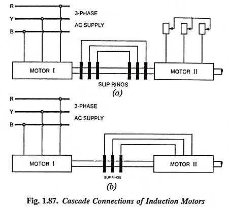
In this method, two motors are required, at least one of which must have a wound rotor. The two motors may be mechanically coupled together to drive a common load. If the stator winding of one of them, a wound rotor motor, is connected to 3-phase ac supply, and its rotor winding is connected to the stator winding of the second motor, the speed of the combination will be determinated by the sum or difference of the number of poles in the two machines. In practice, it is customary, to connect the rotor output of the first machine to the stator of the second machine in such a way that the revolving fields of both are in the same direction; under this condition, the resulting speed will be determined by the following expression.
where
- f is supply frequency,
- P1 and P2 are the number of poles on machines I and II respectively.
For obtaining speed, above normal the torque of the second motor is reversed by simply changing two of the leads of the second motor. This is called the differential cascading and under this condition speed will be given by the expression.
Further speed control, if desired, can be obtained by having second machine also of wound rotor type and inserting control resistance in the rotor circuit of the second machine.
If the two motors have the same number of poles and are connected in cumulative cascade [Eq. (1.77)], they will operate at practically half speed. Since the shaft torque is largely reduced in differential cascade, it is not employed in practice.
The mechanical output of the two machines are approximately in the ratio of
or P1 : P2, i.e., in the ratio of number of poles on the machines.

