Star Winding and Delta Winding:
Star Winding and Delta Winding – The magnitude of earth-fault current for a given fault position within a winding depends upon the winding connections and the method of neutral earthing. The two conditions for earth-fault current to flow in the case of a winding fault to earth are:
- That a path exists for current to flow into and out of the winding.
- That ampere-turns balance is maintained between the windings.
From (a) above obviously it is not necessary for the winding itself to be earthed for fault current to flow, only that the system connected to the winding is earthed. The delta side of a transformer is usually earthed through an earthing transformer.
Star Winding With Resistance Earthed Neutral:
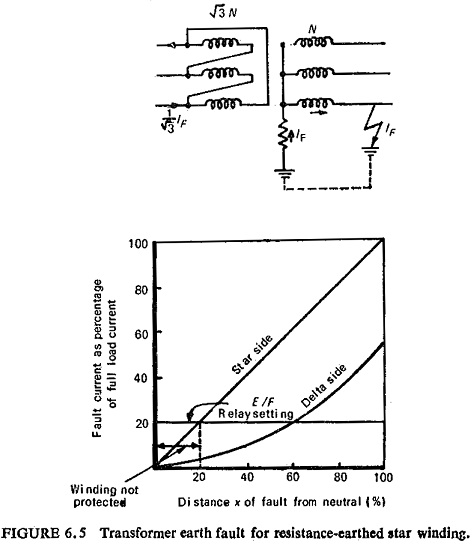
The earth-fault current in this case depends on the value of earthing resistor and is proportional to the distance of the fault from the neutral end of the winding. Considering the case of a delta-star transformer, neutral earthed through a resistor on the secondary side; for a 1:1 voltage ratio the primary to secondary turn ratio is √3:1. For an earth fault (IF) at 100% of the winding on the secondary side the corresponding value on the primary side is 1/√3 times the fault current on the secondary (1/√3) IF.
Now as the fault position on the secondary side varies, the effective ratio of transformation between the primary and the faulted portion of the secondary winding also varies. Hence for an earth fault at x % of the winding on the secondary side [(x/100)IF] the corresponding current on the primary side will be (x/100)2 IF/√3 as the effective turn ratio of primary to secondary now is √3 : x/100. Thus the primary fault current is proportional to the square of the percentage of winding short-circuited. The variation of fault current both in the primary and the secondary windings is shown in Fig. (6.5) for a 1:1 voltage ratio, the resistor is assumed to pass full-load current of the transformer with rated line-neutral voltage.
Star Winding with Neutral Solidly Earthed:
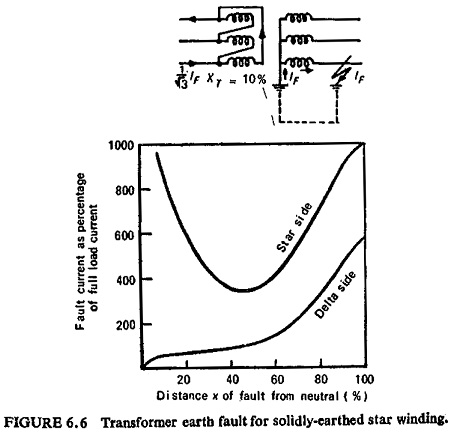
The earth-fault current is limited solely by the winding impedance and the fault current is no longer proportional to the position of the fault. The leakage reactance of the faulted winding in terms of reactance per turn increases the nearer the fault is to the star point, but the reactance of the other winding is effectively reduced owing to the change in transformation ratio so that the fault current reaches a minimum at some point near the middle of the winding. Figure (6.6) shows the transformer earth-fault current on a solidly earthed star winding.
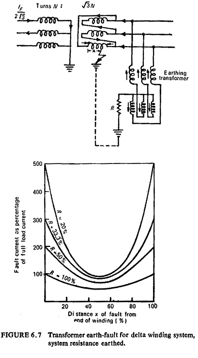
Delta Winding:
The minimum voltage on the delta winding is only half the phase-to-earth voltage and occurs on the midpoint of phase. The high leakage reactance 25 to 50% at midpoint gives fault currents with a solidly-earthed system of 100 to 200% of full load; this divides equally between two phases. If the system is resistance earthed the resistance R should be added vectorially to the high reactance in determining the minimum earth-fault current. However, if the resistor is rated to pass currents of the order of the full-load current of the transformer at rated phase-neutral voltage V the minimum current can be expressed as V/2R for all practical purposes.


