Starting of DC Motors:
At the time of Starting of DC Motors (n = 0), the induced emf of a motor is zero such that the current drawn from rated voltage supply would be
for a shunt motor. The series field resistance would be included in the denominator for a series motor. For large motors the armature resistance may be 0.01 pu or less; even for lower kW motors it ranges from 0.0625 to 0.125. Thus in full-voltage Starting of DC Motors, the armature current can be several times (about 100 times for large motors) the rated value.
For several reasons mentioned below such a large current cannot be allowed to flow in a motor even for the short starting period.
- It would cause intolerably heavy sparking at the brushes which may destroy the commutator and brush-gear.
- Sudden development of large torque causes mechanical shock to the shaft, reducing its life.
- Such heavy current cannot be generally permitted to be drawn from the source of supply.
For the above-mentioned reasons all motors, except for small and fractional-kW motors, must be started with external resistance included in armature circuit to limit the starting current to safe values. Where variable-voltage dc supply is available, e.g. in the Ward-Leonard speed control scheme, this can be used for motor starting and no starting resistance would be needed.
One point in favour of direct starting must be mentioned here. Since the motor torque with direct start is much higher, the motor starts much more quickly. As a consequence the Joule input per start is much less than that with resistance start. This would be helpful in repeated starting—saving energy and causing less temperature rise.
Maximum allowable starting current is not more than 1.5 to 2.0 times the rated value. These values are safe and yet at the same time permit a high starting torque for quick acceleration of the motor. Where a variable-voltage supply is available for speed control, starting poses no problem at all.
In shunt motor starting, the shunt field must be switched on first so that steady field current is already established before the armature with starting resistance in the circuit is switched on to supply. This is because the shunt field has a high inductance and current through it (and the machine flux) builds slowly resulting in a low starting torque during the initial time of shunt field transient if both field and armature are switched on simultaneously to supply. Also all regulator resistance in the shunt field circuit must be fully cut out to give high field current and consequently high starting torque.
The Starting of DC Motors resistance is arranged in steps and is gradually cut out as the motor accelerates so as to maintain a high average torque during starting.
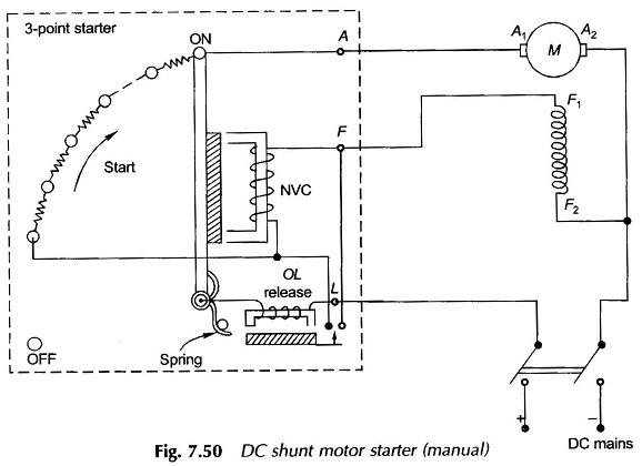
The connection diagram of a manual face plate starter of a dc shunt motor is shown in Fig. 7.50. The starter handle is shown in its ON position — starting resistance is cut out, which gets included in the field circuit.
Two Protective Devices in a DC Motor Starter:
- NVC (no volt coil): In case of failure of field current (due to accidental or otherwise open circuiting), this coil releases the handle (held electromagneti-cally), which goes back to the OFF position under the spring action.
- OL (over load) release: The contact of this relay at armature current above a certain value (over load/short circuit) the NVC ends, again bringing the handle to OFF position.
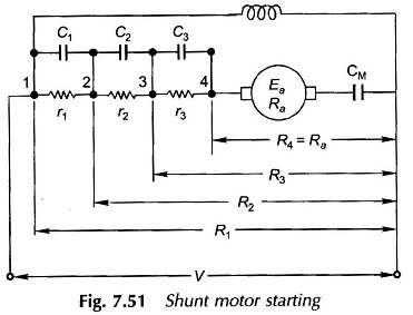
The modem practice is to use a push-button type automatic starter in industries. Automatic starters carry out essentially the same functions as the manual ones with electromagnetic relays that short out sections of the robust metallic starting resistors either in a predetermined time sequence or when the armature current has dropped to a preset value. Such an arrangement is shown in Fig. 7.51. Most automatic starters embody extra control and safety features.
Starter Step Calculation for DC Shunt Motor:
From Fig. 7.51 it is seen that the instant the starter is moved to stud 1 or contactor CM is closed, the current in the circuit reaches a value I1, designated as the upper current limit, given by
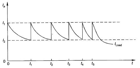
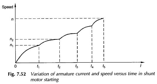
Thereafter the current value decreases as the motor speeds up and its back emf rises as shown in Fig. 7.52. The current is allowed to reduce to I2, the lower current limit, given by
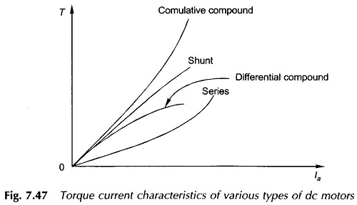
where Ea(n1) is the back emf at speed n1 reached by the motor. At this instant the starter is moved to stud 2 or contactor C1 is closed. The current increases instantaneously to I1 as shown in Fig. 7.47 and satisfies the relationship
From Eqs. (7.63) ad (7.64),
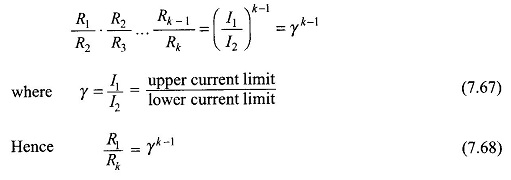
By induction, for a k-stud ((k — 1) sections of external resistance) starter,
It immediately follows from Eq. (7.66) that
From Fig. 7.51 it is obvious that
Figure 7.52 shows the plot of the armature current and speed versus time as the starter resistance is cut out in steps. During waiting time at each step, the current falls and the speed rises exponentially according to a single dominant time-constant. This is the reason why the waiting time at each step progressively reduces as is easily evident from Fig. 7.52.
Once the designer has selected the upper and lower limits of armature currents during starting, starter step calculations can proceed on the following lines:
- From Eq. (7.62) calculate R1.
- From Eq. (7.69) calculate the number of steps k choosing the nearest integral value.
- Calculate resistances R1, R2 … from Eq. (7.66). From these the resistance values of various sections of the Starting of DC Motors can be found out.
Sometimes the number of sections are specified in addition to the upper current limit. This problem can be handled by a slightly different manipulation of Eqs (7.62) to (7.69).
