Static Kramer Drive:
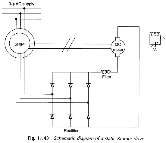
The Static Kramer drive system which consists of variable-speed drive system shown in Fig. 11.43 consists of a slipring induction motor and a rectifier-fed dc motor. The machines are connected electrically in cascade.
The slip power recovery takes place through the rectifier and the auxiliary dc motor. Torque supplied to the load is sum of torque produced by induction and dc motors. Speed control is obtained by controlling field current of dc motor.
If larger speed range is required, diode bridge can be replaced by a thyristor bridge. Speed can now be controlled up to standstill.
As a Static Kramer Drive system possesses no line-commutated inverter, it causes less reactive power and smaller harmonic contents of currents than a static Scherbius system. But it has maintenance problems caused by the brushes and commutator of an auxiliary dc motor and the disadvantage of a large moment of inertia.
It is observed from the above discussion that for implementation of speed-control of the induction motor, one needs to understand the operation of the inverter which transforms the dc power into variable-frequency ac power. Before taking this up, the phase-control scheme for controlling the stator voltage will first be considered.
