Static Scherbius Drive:
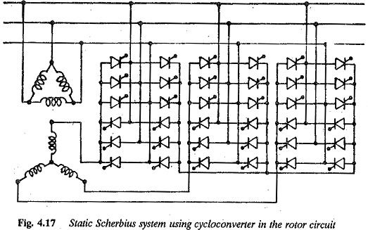
The main limitation of the Kraemer drive discussed is the operation at sub-synchronous range due to diode rectifier. Super synchronous speeds can be achieved if the power is fed to the rotor from the ac mains. This can be made possible by replacing the converter cascade by a Static Scherbius Drive system using Cycloconverter in rotor circuit, as shown in Fig 4.17.
A cycloconverter allows power flow in either direction making the drive operate at both sub and super synchronous speeds. However, the converter becomes costly and has a complex control. The current in the rotor circuit is nearly sinusoidal. The torque pulsations and other reactions are minimal. The performance of the drive improves with respect to additional losses and torque pulsations. A smooth transition is possible from sub to super synchronous speeds without any commutation problems. Speed reversal is not possible. A step up transformer may be interposed between the lines and the converter to reduce the voltage rating of the converter.
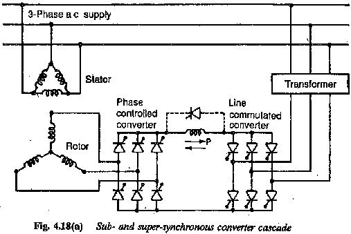
Static Scherbius Drive, with power flow to and from the rotor, can also be realized by replacing the diode rectifier on the rotor side by means of a controlled bridge rectifier using thyristors, as shown in Fig. 4.18. This provides speeds below and above synchronous speed. The effects of non-sinusoidal rotor current are present. In addition the commutation of the bridge rectifier at very small slips (near synchronous speed) poses problems.
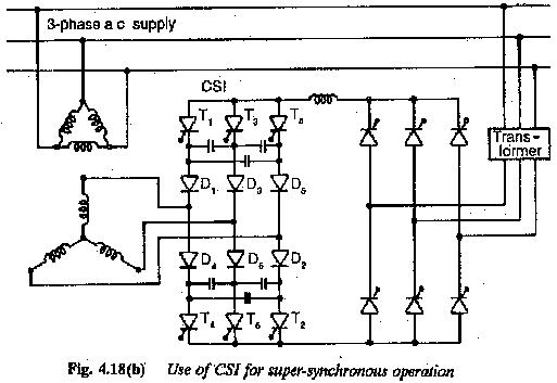
Either forced commutation or artificial commutation of the thyristors is employed at and about synchronous speed. These methods are shown in Fig. 4.18. A current source inverter can be advantageously employed to obtain a Static Scherbius drive.


