Strip Chart Recorder Working Principle:
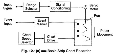
Strip Chart Recorder Working Principle are those in which data is recorded on a continuous roll of chart paper moving at a constant speed. The recorder records the variation of one of more variables with respect to time. The basic element of a Strip Chart Recorder Working Principle consists of a pen (stylus) used for making marks on a movable paper, a pen (stylus) driving system, a vertically moving long roll of chart paper and chart paper drive mechanism and a chart speed selector switch, (as shown in Fig. 12.1(a)).
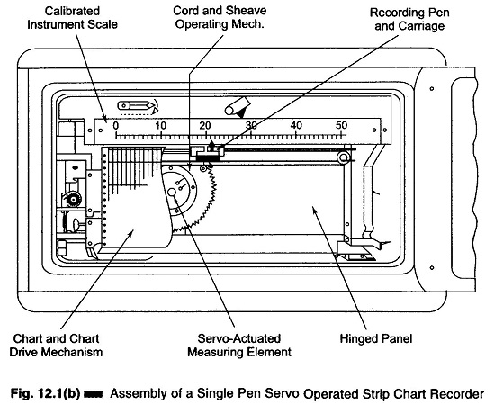
Most recorders use a pointer attached to the stylus, so that the instantaneous value of the quantity being recorded can be measured directly on a calibrated scale. The assembly of a Strip Chart Recorder Working Principle is shown in Fig. 12.1(b). This recorder uses a single pen and is servo driven.
Most strip chart recorders use a servo feedback system, to ensure that the displacement of the pen (stylus) across the paper tracks the input voltage in the required frequency range.
A potentiometer system is generally used to measure the position of the writing head (stylus).
The chart paper drive system generally consists of a stepping motor which controls the movement of the chart paper at a uniform rate.
The data on the strip chart paper can be recorded by various methods.
1. Pen and Ink Stylus:
The ink is supplied to the stylus from a refillable reservoir by capillary action. Modern technology has replaced these pens by disposable fibre tip pens. In addition, multichannel operation can be performed, i.e. at any instant, a maximum of six pens can be used to record data. When using multiple pens, staggering of the pens are necessary to avoid mechanical interference.
2. Impact Printing:
The original impact system consisted of a carbon ribbon placed between the pointer mechanism and paper, which provided the ink for recording data. The mark was made on the paper by pressing the pointer mechanism on it. The advantage of impact printing over the pen and ink method is that, it can record data on up to 20 variables simultaneously. This is achieved with the help of a wheel with an associated ink pad which provides the ink for the symbol on the wheel. The wheel is moved across the paper in response to the variable being recorded.
In some mechanisms, pressure sensitive paper is used. The markings on the paper are done with chopper bar, which applies the pressure on the paper. The frequency of the chopper bar is once per second.
3. Thermal Writing:
In this system, a special movable pen which is thermally heated by passing an electric current through it is used. This system requires a thermally sensitive paper which changes its colour on application of heat.
4. Electric Writing:
This technique is based on the principle of electrostatics.
In this method, a special chart paper is used. This paper consists of a paper base coated with a layer of coloured dye (black, blue or red), which in turn is coated with a thin surface of aluminium.
The stylus (pen) consists of a tungsten wire moving over the aluminium surface. Markings on the paper are achieved by applying a potential of 35 V to the stylus. This causes an electric discharge which removes the aluminium, revealing the coloured dye.
5. Optical Writing:
In this technique of writing, a special photo sensitive chart paper, sensitive to ultra violet light is used. This technique is mostly used in galvanometer system.
Ultra violet light is used to reduce unwanted effects from ambient light. The paper can be developed in daylight or under artificial light without the need for special chemicals, which is not possible if ordinary light is used.
Most recorders use a pointer attached to the stylus. This pointer moves over a calibrated scale giving the instantaneous value of the quantity being recorded.
Paper drive system: The paper drive system should move the paper at a uniform speed. A spring wound mechanism may be used in most A synchronous motor is used for driving the paper.
Chart speed: Chart speed is a term used to express the rate at which the recording paper in a strip chart recorder moves. It is expressed in in/s or mm/s and is determined by mechanical gear trains. If –the chart speed is known, the period of the recorded signal can be calculated as
and frequency can be determined as f = 1/period.


