Summing, Scaling and Averaging Amplifier:
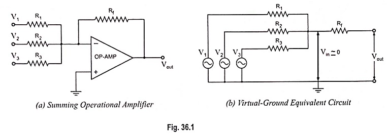
The most useful of the op-amp circuits employed in analog computers is the summing amplifier circuit. This circuit can be used to add ac or dc signals. This circuit provides an output voltage proportional to or equal to the algebraic sum of two or more input voltages each multiplied by a constant gain factor. Three-input summing circuit is shown in Fig. 36.1 (a).
Using the virtual equivalent circuit, as shown in Fig. 36.1 (b), the output voltage can be given in terms of inputs as
Op-amp summing amplifiers are also called mixers. One of the advantages of inverting op-amp mixers is that there is no interaction between the inputs. The inverting input is a virtual ground. This prevents one input signal from appearing at the other inputs.
The circuit shown in Fig. 36.1 (a) can be used as a summing amplifier, scaling amplifier or averaging amplifier.
Equation (36.2) reveals that the output voltage is equal to the negative sum of all input voltages, hence the circuit acts as a summing amplifier.
If each input voltage is amplified by a different factor i.e., weighted differently at the output, the circuit becomes a scaling or weighted amplifier.
The output voltage of the scaling amplifier is given by Eq. (36.1) where
The circuit shown in Fig. 36.1 (a) can be used as an averaging circuit, which gives output voltage equal to average of all the input voltages. The modification required in the circuit are of equalizing all the input resistors R1, R2 and R3 i.e., R1 = R2 = R3 = R (say) and making gain equal to one over the number of inputs i.e., = Rf/R = 1/n where ii is the number of inputs.
For example, for three inputs the output voltage,
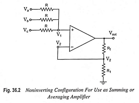
Summing or averaging amplifier circuit (Fig. 36.2) can be designed in noninverting configuration by selecting appropriate values of resistors i.e., Rf and R1.
Using the superposition theorem, the voltage V1 at the noninverting terminal is
Hence the output voltage is
Equation (36.5) reveals that the output voltage is equal to the product of average of all input voltages and the gain of the circuit (1 + Rf/R1). Hence it is referred to as an averaging amplifier.
The gain (1 + Rf/R1) can be set to any value as per application need. For unity gain i.e., when (1 + Rf/R1) = 1, the circuit will give average of all the inputs.
In case the gain of the circuit (i.e., 1 + Rf/R1) is made equal to the number of inputs, the output voltage will become equal to the sum of all the input voltages
Hence the circuit is called a noninverting summing amplifier.
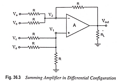
Summing Amplifier in Differential Configuration: A four-input summing amplifier (Fig. 36.3) may be constructed using the basic differential amplifier shown in Fig. 34.29 by adding two input sources, one each to the inverting and noninverting input terminals through resistor R.
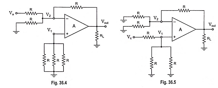
The circuit output can be determined by using the superposition theorem. For instance, for determination of output voltage due to Va alone, reduce all other input voltages Vb, Vc and Vd to zero, as shown in Fig. 36.4. Infact, this circuit is an inverting amplifier in which the inverting input terminal is at virtual ground (i.e., V2 = 0).
So the output voltage, Vout a = -R/R Va = -Va
Similarly the output voltage due to Vb alone, Vout b = -Vb
Now if input voltages Va, Vb and Vd are made zero, the circuit shown in Fig. 36.3 becomes a noninverting amplifier (Fig. 36.5) in which the voltage V1 at the noninverting input terminal is
So the output voltage due to Vc alone,
Similarly, the output voltage due to Vd alone,
The net output voltage is thus
The above equation reveals that the output voltage is equal to the sum of the input voltages applied to the noninverting input terminal plus the negative sum of the input voltages applied to the inverting input terminal. Even though in the circuit shown in Fig. 36.3 the gain of the summing amplifier is unity, any scale factor can be used for the inputs by selecting proper external resistors.
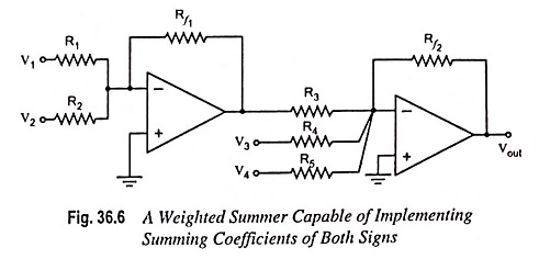
Weighted Summer Capable of Implementing Summing Coefficients of Both Signs: The weighted summing amplifier shown in Fig. 36.1 (a) has the limitation that all the summing coefficients are of the same sign. Sometimes signals with opposite signs need to be summed up. Such a function can be implemented using two op-amps, as shown in Fig. 36.6. Assuming ideal op-amps, it can be easily shown that the output voltage is given by
