Thermistor Working Principle:
Thermistor Working Principle – The electrical resistance of most materials changes with temperature. By selecting materials that are very temperature sensitive, devices that are useful in temperature control circuits and for temperature measurements can be made.
Thermistor (THERMally sensitive resISTOR) are non-metallic resistors (semiconductor material), made by sintering mixtures of metallic oxides such as manganese, nickel, cobalt, copper and uranium.
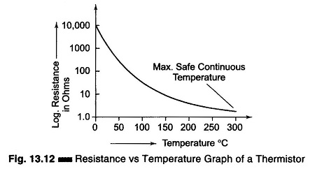
Thermistors have a Negative Temperature Coefficient (NTC), i.e. resistance decreases as temperature rises. Figure 13.12 shows a graph of resistance vs temperature for a thermistor. The resistance at room temperature (25°C) for typical commercial units ranges from 100 Ω to 10 Ω They are suitable for use only up to about 800°C. In some cases, the resistance of thermistors at room temperature may decrease by 5% for each 1°C rise in temperature. This high sensitivity to temperature changes makes the thermistor extremely useful for precision temperature measurements, control and compensation.
The smallest thermistors are made in the form of beads. Some are as small as 0.15 mm (0.006 in.) in diameter. These may come in a glass coating or sealed in the tip of solid glass probes. Glass probes have a diameter of about 2.5 mm and a length which varies from 6 – 50 mm. The probes are used for measuring the temperature of liquids. The resistance ranges from 300 Ω to 100 MΩ.
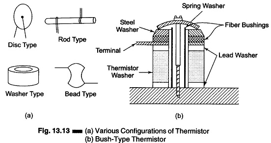
Where greater power dissipations is required, thermistors may be obtained in disc, washer or rod forms.
Disc thermistors about 10 mm in diameter, either self supporting or mounted on a small plate, are mainly used for temperature control. These thermistors are made by pressing themistors material under several tons of pressure in a round die to produce flat pieces 1.25 – 25 mm in diameter and 0.25 – 0.75 mm thick, having resistance values of 1 Ω to 1 MΩ. These are sintered and coated with silver on two flat surfaces.
Washer thermistors are made like disc thermistors, except that a hole is formed in the centre in order to make them suitable for mounting on a bolt. Rod thermistors are extruded through dies to make long cylindrical units of 1.25, 2.75, and 4.25 mm in diameter and 12.5 – 50 min long. Leads are attached to the end of the rods. Their resistance usually varies from 1 – 50 kΩ
The advantage of rod thermistor working principle over other configurations is the ability to produce high resistance units with moderately high power handling capability.
Thermistors can be connected in series/parallel combinations for applications requiring increased power handling capability. High resistance units find application in measurements that employ low lead wires or cables.
Thermistors are chemically stable and can be used in nuclear environments. Their wide range of characteristics also permits them to be used in limiting and regulation circuits, as time delays, for integration of power pulses, and as memory units.
Typical thermistor configurations are as shown in Fig. 13.13(a). Figure 13.13(b) shows a bush type thermistor.
A thermistor in one arm of a Wheatstone bridge provides precise temperature information. Accuracy is limited, in most applications, only by the readout devices.
Thermistors are non-linear devices over a temperature range, although now units with better than 0.2% linearity over the 0-100°C temperature range are available. The typical sensitivity of a thermistor is approximately 3 mV/°C at 200°C.
Advantages of Thermistor:
- Small size and low cost.
- Fast response over narrow temperature range.
- Good sensitivity in the NTC region.
- Cold junction compensation not required due to dependence of resistance on absolute temperature.
- Contact and lead resistance problems not encountered due to large Rth (resistance).
Limitations of Thermistor:
- Non-linearity in resistance vs temperature characteristics.
- Unsuitable for wide temperature range.
- Very low excitation current to avoid self-heating.
- Need of shielded power lines, filters, etc. due to high resistance.

