Thermocouple Principle and Types of Thermocouple:
Thermocouple Principle consists of a junction of two dissimilar wires, so chosen that a voltage is generated by heating the junction. The output of a thermocouple is delivered to a sensitive dc microammeter.
(Calibration is made with dc or with a low frequency, such as 50 cycles, and applies for all frequencies for which the skin effect in the heater is not appreciable. Thermocouple instruments are the standard means for measuring current at radio frequencies.)
The generation of dc voltage by heating the junction is called thermoelectric action and the device is called a thermocouple.
Different Types of Thermocouple:
In a thermocouple instrument, the current to be measured is used to heat the junction of two metals. These two metals form a thermocouple and they have the property that when the junction is heated it produces a voltage proportional to the heating effect. This output voltage drives a sensitive dc microammeter, giving a reading proportional to the magnitude of the ac input.
The alternating current heats the junction; the heating effect is the same for both half cycles of the ac, because the direction of potential drop (or polarity) is always be the same. The various, types of Thermocouple Principle are as follows.
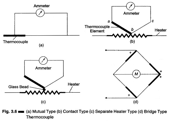
Mutual Type (Fig. 3.6 (a))
In this type, the alternating current passes through the thermocouple itself and not through a heater wire. It has the disadvantages that the meter shunts the thermocouple.
Contact Type (Fig. 3.6 (b))
This is less sensitive than the mutual type. In the cOntact type there are separate thermocouple leads which conduct away the heat from the heater wire.
Separate Heater Type (Fig. 3.6 (c))
In this arrangement, the thermocouple is held near the heater, bin insulated from it by a glass bead. This makes the instrument sluggish and also less sensitive because of temperature drop in the glass bead. The separate type is useful for certain applications, like RF current measurements. To avoid loss of heat’ by radiation, the thermocouple arrangement is placed in a vacuum in order to increase its sensitivity.
Bridge Type (Fig. 3.6 (d))
This has the high sensitivity of the mutual type and yet avoids the shunting effect of the microammeter.
The sensitivity of a thermocouple is increased by placing it in a vacuum since loss of heat by conduction is avoided, and the absence of oxygen permits operation at a much higher temperature. A vacuum thermocouple can be designed to give a full scale deflection of approximately 1 mA. A similar bridge arrangement in air would require about 100 mA for full scale deflection.
Material commonly used to form a thermocouple are constantan against copper, manganin or a platinum alloy. Such a junction gives a thermal emf of approximately 45 μV/°C.
The heating element of open air heaters is typically a non-corroding platinum alloy. Carbon filament heaters are used in vacuum type.
Thermocouple heaters operate so close to the burnout point under normal conditions, that they can withstand only overloads: without damage, commonly up to 50%. This is one of the limitations of the thermocouple instrument.
(Commonly used metal Combinations are copper-constantan, iron-constantan, chromel-constantan, chromel-alumel, and platinum-rhodium. Tables are available that show the voltages produced by each of the various metal combination at specific temperatures)
Limitations of Thermocouple:
Following are the limitations of Thermocouple Principle
- Heaters can stand only small overload.
- A rise in temperature (higher operating temperatures) causes a change in the resistance of the heater.
- Presence of harmonics changes meter reading, because the heating effect is proportional to the square of current.
This can be understood by the following example.
The effective value of input wave is
where
- I1 is the fundamental
- I2 is second harmonic
- I3 is third harmonic
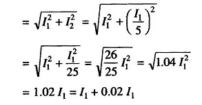
If 20% harmonics are present, then I2 = I1/5
Therefore, the error in the current reading if 20% harmonics is present, is calculated as follows. Therefore effective value of input wave
But 0.02 = 2%. Hence 20% harmonics increase the error by 2%.

