Three Phase Semi Converter feeding Separately Excited DC Motor:
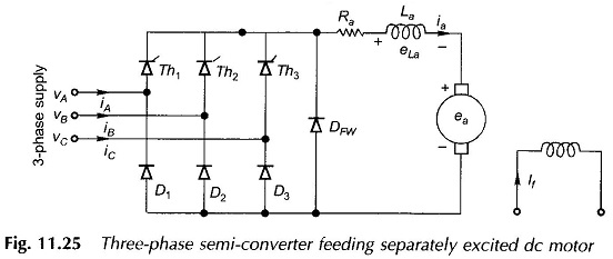
Large-kW motors are fed from 3-phase supply through three Phase Converters. In a three Phase Semi Converter, the ripple frequency of the motor terminal voltage is higher than that in the single-phase converter, as a result the filtering requirements for smoothing out the motor current are less and the current is mostly continuous. Three Phase Semi Converter could be half-wave, semi-converter, full-converter and dual-converter. The 3-phase half-wave converter is useless for most practical purposes because the supply currents contain dc component. Semi- and full-converters are most common in use. A dual-converter is employed for reversible drives with a power rating up to several MW. For want of space only the three Phase Semi Converter feeding Separately Excited DC Motor will be described here, as shown in the circuit diagram of Fig. 11.25.
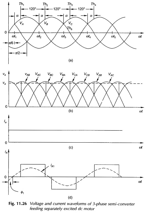
Figure 11.26(a) shows the phase voltage waveforms applied to the converter. Convenient references for the thyristor firing angles are ωt1, ωt2, ωt3 … spaced 120° apart. Let the firing angle be α. The three thyristors fire in sequence with a time spacing of 120° as shown in the figure. After Th1 fires, diodes D2 or D3 conducts depending upon which voltage is more positive of VAB and VAC. For the value of α chosen, it may be immediately seen from Fig. 11.26(b) that diode D2 conducts up to 90° beyond which D3 conducts till Th2 fires. Then D3 and D1 conduct till Th3 fires followed by D1, D2 conducting in sequence. This process then repeats resulting in the voltage waveform of va as shown in Fig. 11.26(b). For this value of α, the freewheeling diode is not called upon to conduct the armature current. The armature current ia and line current iA are shown in Figs. 11.26(c) and 11.26(d) respectively. The fundamental iA1 of the line current lags by a small angle Φ1 resulting in less than unity power factor.
For a firing angle α = 60°, only one diode conducts during the conduction period of a thyristor. The conduction sequence is now Th1D3, Th2D1, Th3D2. For larger values of α, VAC becomes negative before Th2 fires resulting in interruption of line current so that ia flows through DFW, the free-wheeling diode.
If the free-wheeling diode is not used, free-wheeling takes place through the diode and thyristor of a given branch, e.g. after D3 stops conducting, free-wheeling occurs through Th1D1.
The average value of armature voltage Va reduces continuously as α is increased. Simultaneously, the lag angle Φ1 of iA1 increases resulting in deterioration of the line power factor.
The average of νa, the armature terminal voltage is derived below:
Let the supply voltages be
For the case of continuous armature current:
or
It must be noted that Eqs (11.12a) and (11.12b) are identical expressions.
The expression of Eq. (11.10) for average motor speed now modifies to


