Three pulse converter with freewheeling diode:
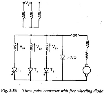
A Three pulse converter with freewheeling diode across the load terminals is depicted in Fig. 3.56. The diode is meant to provide an alternative path for the load current, which would otherwise have flown through the converter.
The diode becomes positively biased when the load voltage becomes negative, and starts conducting. At this time the thyristor of the converter is reverse biased and stops conduction. Thus, negative swings of the load voltage are avoided and it is zero during free wheeling.
Inversion is not possible. In the converter, the FWD becomes effective only for those firing angles for which the load voltage tends to become negative. For firing angles, up to π/6, the diode does not get a forward voltage as the load voltage has no tendency to become negative. For a 3 pulse converter the diode is effective for α > π / 6.
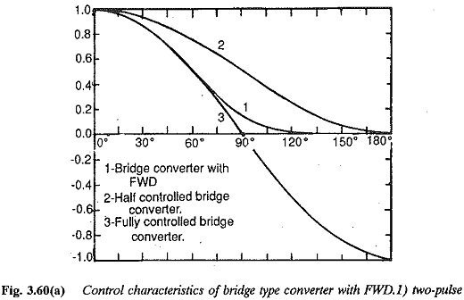
The effective variation of α is only from 0 to 5π /6. The control characteristic is shown in Fig. 3.60. Until the free wheeling diode takes part in conduction, i.e. 0 < α < π /6 , the converter operates as a two quadrant one and there is thus no reactive power saving in this range of angles.
The terminal voltage is affected in the working range by the drops in the input reactances, resistance and device drops. The free wheeling diode improves the performance in the same way as in the case of a half controlled rectifier. The input current pulses have a conduction angle which decreases with increasing α. During free wheeling, no current is drawn from the mains when the load voltage is zero. This helps in reducing the control reactive power requirement. The current in mid point converters flows from line to neutral. The input power factor and harmonics are the same as in the case of half controlled converters. The overlap due to commutation and the necessary reactive power for commutation is the same as in the fully controlled case.
Advantages of Three pulse converter with freewheeling diode:
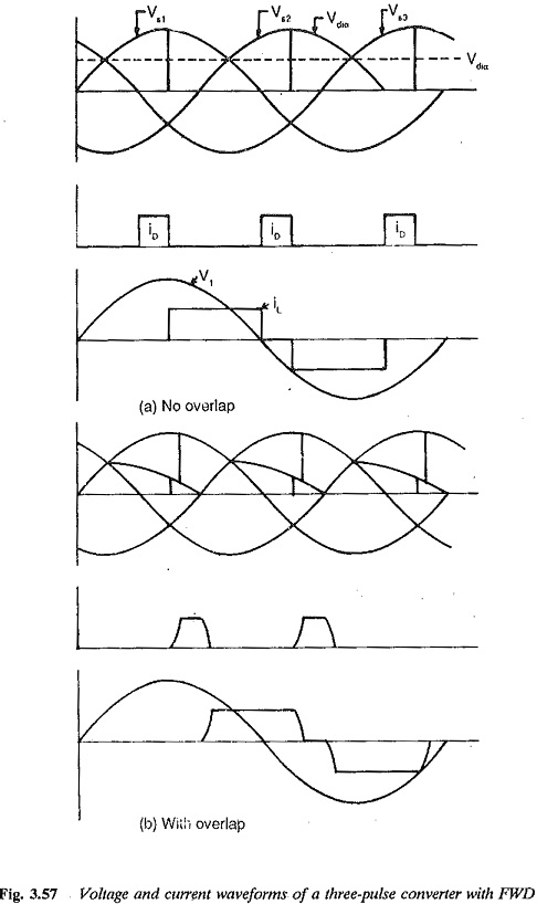
The advantages of the converter are available only when the diode participates in conduction, i.e. α ≥ 60°. The voltage and current waveforms are shown in Fig. 3.57.


