Thyristors Articles:
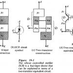
Silicon Controlled Rectifier Principle Operation: Silicon Controlled Rectifier Principle Operation (SCR) consists of four layers of semiconductor material, alternately p-type and n-type as illustrated in Fig. 19-1(a). Because of its construction, the SCR is sometimes referred to as a four-layer diode, … (Read More)
SCR Control Circuit Diagram: Pulse Control – The simplest of SCR Control Circuit Diagram is shown in Fig. 19-8(a). If SCR1 was an ordinary rectifier, the ac supply voltage would be half- wave rectified and only the positive half-cycles would appear … (Read More)
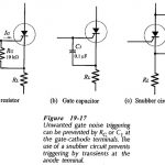
SCR Applications Circuits: An SCR circuit is stable when it operates correctly: switching on and off only at the desired instants. Unwanted triggering (also called false triggering) can be produced by noise voltages at the gate, transient … (Read More)
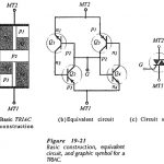
TRIAC Operation and Characteristics: The basic construction, equivalent circuit, graphic symbol and TRIAC Operation and Characteristics are shown in Fig. 19-21. The TRIAC behaves as two inverse-parallel connected SCRs with a single gate terminal. Sections n1,p2,n3, and p3, in Fig. 19-21(a) form … (Read More)
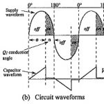
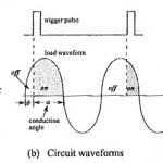
TRIAC Control Circuit Diagram: A TRIAC Control Circuit Diagram that allows approximately 180° of phase control is shown in Fig. 19-27(a). The waveforms in Fig. 19-27(b) illustrate the circuit operation. With the TRIAC (Q1) off at the beginning of the supply … (Read More)
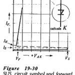
Silicon Unilateral Switch: The Silicon Unilateral Switch (SUS), also known as a four layer diode and as a Schokley diode, can be treated as a low-current SCR without a gate terminal. Figure 19-30 shows the Silicon Unilateral Switch circuit symbol and … (Read More)
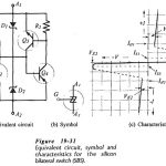
Silicon Bilateral Switch: It might be convenient to think of a Silicon Bilateral Switch (SBS) as an SUS with a gate terminal, or as a low-current TRIAC. However, the SBS is not simply another four-layer device. Silicon bilateral switches are actually integrated … (Read More)
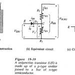
UJT Circuit Diagram: UJT Circuit Diagram Operation : The Unijunction transistor (UJT) consists of a bar of lightly-doped n-type silicon with a block of p-type material on one side, .The end terminals of the bar are identified as Base … (Read More)
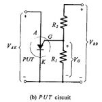
Programmable Unijunction Transistor: PUT Operation – The Programmable Unijunction Transistor (PUT) is actually an SCR-type device used to simulate a UJT. The interbase resistance (RBB) and the intrinsic standoff ratio (η) can be programmed to any desired values by selecting two … (Read More)