Tie Set Matrix(Link Currents):
Tie Set Matrix – For a given tree of a graph, addition of each link between any two nodes forms a loop called the fundamental loop. In a loop there exists a closed path and a circulating current, which is called the link current. The current in any branch of a graph can be found by using link currents.
The fundamental loop formed by one link has a unique path in the tree joining the two nodes of the link. This loop is also called f-loop or a tie set.
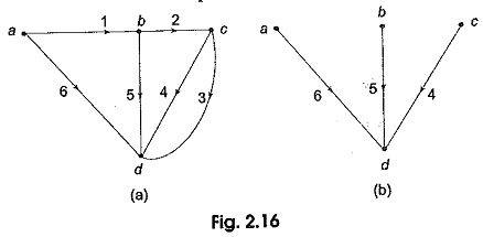
Consider a connected graph shown in Fig. 2.16 (a). It has four nodes and six branches, One of its trees is arbitrarily chosen and is shown in Fig. 2.16 (b). The twigs of this tree are branches 4, 5 and 6. The links corresponding to this tree are branches 1, 2 and 3. Every link defines a fundamental loop of the network.
No. of nodes it = 4
No. of branches b = 6
No. of tree branches or twigs = n — 1 = 3
No. of link branches I = b — (n — 1) = 3
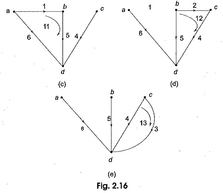
Let i1, i2,….i6 be the branch currents with directions as shown in Fig. 2.16 (a). Let us add a link in its proper place to the tree as shown in 2.16 (c). It is seen that a loop .I1 is formed by the branches 1, 5 and 6. There is a formation of link current, let this current be I1. This current passes through the branches 1, 5 and 6. By convention a fundamental loop is given the same orientation as its defining link, i.e. the link current I1 coincides with the branch current direction i1 in ab. A tie set can also be defined as the set of branches that forms a closed loop in which the link current flows. By adding the other link branches 2 and 3, we can form two more fundamental loops or f-loops with link currents I2 and I3 respectively as shown in Figs 2.16 (d) and (e).
Tie Set Matrix
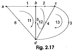
Kirchhoff’s voltage law can be applied to the f-loops to get a set of linearly independent equations. Consider Fig. 2.17.
There are three fundamental loops I1, I2 and I3 corresponding to the link branches 1, 2 and 3 respectively. If V1, V2,…V6 are the branch voltages the KVL equations for the three f-loops can be written as
In order to apply KVL to each fundamental loop, we take the reference direction of the loop which coincides with the reference direction of the link defining the loop.
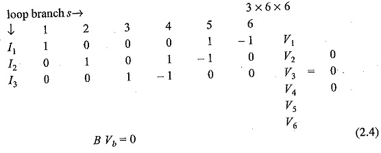
The above equation can be written in matrix form as
where B is an I x b matrix called the tie set matrix or fundamental loop matrix and Vb is a column vector of branch voltages.
The tie set matrix B is written in a compact form as B[bij] (2.5)
The element bij of B is defined as
bij = 1 when branch bj is in the f-loop Ii(loop current) and their reference directions coincide.
bij = —1 when branch bj is in the f-loop Iiloop current) and their reference directions are opposite.
bij = 0 when branch bj is not in the f-loop Ii.
Tie Set Matrix and Branch Currents
It is possible to express branch currents as a linear combination of link current using matrix B.
If IB and II represents the branch current matrix and loop current matrix respectively and B is the tie set matrix, then
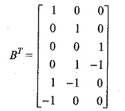
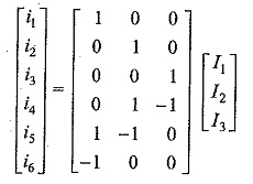
where [BT] is the transpose of the matrix [B]. Equation (6) is known as link current transformation equation.
Consider the tie set matrix of Fig. 2.17
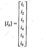
The branch current vector [Ib] is a column vector.
The loop current vector [IL] is a column vector
Therefore the link current transformation equation is given by [Ib] = [BT] [IL]
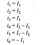
The branch currents are
