Transformer Efficiency Formula:
Power and distribution transformers are designed to operate under conditions of constant rms voltage and frequency and so the efficiency and voltage regulation are of prime importance. Transformer Efficiency Formula is the rated capacity of a transformer is defined as the product of rated voltage and full load current on the output side. The power output depends upon the power factor of the load.
The efficiency η of a transformer is defined as the ratio of the useful power output to the input power.
Thus
The Efficiency of Transformer is in the range of 96-99%. It is of no use trying to determine it by measuring the output and input under load conditions because the wattmeter readings are liable to have an error of 1-2%. The best and accurate method of determining Efficiency of Transformer would be to find the losses from the OC and SC tests. With this data efficiency can then be calculated Transformer Efficiency Formula as
In Eq. (3.54) the effect of meter readings is confined to losses only so that the overall Transformer Efficiency Formula can be obtained from it is far more accurate than that obtained by direct loading.
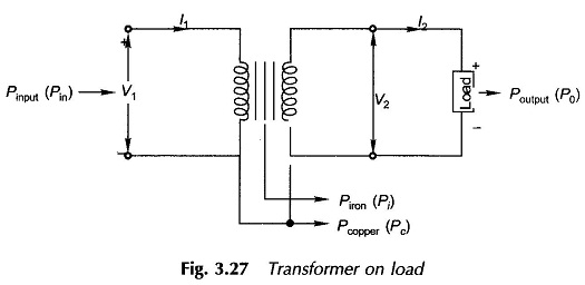
Various losses in a transformer have already discussed and the two important losses (Iron Loss in Transformer Pi and Copper Loss in Transformer Pc) are shown in Fig. 3.27 of a loaded transformer.
Effect of Load and Load Power Factor:
The iron (core) losses depend upon the flux density and so on the induced emf. As E1 ≈ V1 at all loads, these losses can be regarded as constant (independent of load) for constant primary voltage.
Copper losses in the two windings are
where Req(2) = equivalent resistance referred to the secondary side. Thus it is found that copper losses vary as the square of the load current.
where V2 is the rated secondary voltage. It varies slightly with the load but the variation is so small (about 3-5%) that it can be neglected for computing efficiency.
Equation (3.55) shows that for a given power factor, Efficiency of Transformer varies with load current. It can be written as
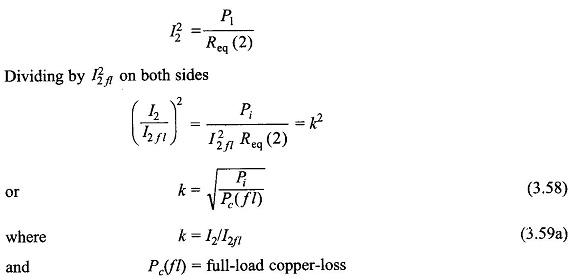
For maximum value of η for given cos θ2 (pf), the denominator of Eq. (3.56) must have the least value. The condition for maximum η, obtained by differentiating the denominator and equating it to zero, is
It means that the efficiency is maximum at a load when the copper-loss (variable loss) equals the core-loss (constant loss). Thus for maximum Transformer Efficiency Formula is given by,
Thus the efficiency is maximum at a fractional load current given by Eq. (3.59a). Multiplying the numerator and denominator of Eq. (3.59a) by rated V2
Thus the maximum efficiency is given at a load k(V2I2fl) or kS2, where S2, is VA (or kVA) rating of the transformer. The expression for maximum Transformer Efficiency Formula is given by
It can be easily observed from Eq. (3.60) that ηmax increases with increasing pf (cos θ2) and is the highest at unity pf. Also ηmax = 0 when cos θ = 0, i.e. at zero pf (purely reactive load). Therefore, knowledge of transformer losses is as important as its efficiency.
Power transformers used for bulk power transmission are operated near about full load at all times and are therefore designed to have maximum efficiency at full-load. On the other hand, the distribution transformers supply load which varies over the day through a wide range. Such transformers are, therefore, designed to have maximum efficiency at about three-fourths the full load.
All Day Efficiency of Transformer:
The All Day Efficiency of Transformer is the ratio of the total energy output (kWh) in a 24-h day to the total energy input in the same time.
Since the core losses are constant independent of the load, the all-day efficiency of a transformer is dependent upon the load cycle; but no prediction can be made on the basis of the load factor (average load/peak load). It is an important figure of merit for distribution transformers which feed daily load cycle varying over a wide load range. Higher energy efficiencies are achieved by designing distribution transformers to yield maximum (power) efficiency at less than full load (usually about 70% of the full load). This is achieved by restricting the core flux density to lower values by using a relatively larger core cross-section. (It means a larger iron/copper weight ratio.)


