How does a Transformer Work and Purpose of Transformer:
How does a Transformer Work – A Transformer Circuit is a static device comprising coils coupled through a magnetic medium connecting two ports at different voltage levels. In an electric system allowing the interchange of electrical energy between the ports in either direction via the magnetic field. The transformer is one of the most important component of a variety of electrical circuits ranging from low-power, low-current electronic and control circuits to ultra high-voltage power systems. Transformers are built in an astonishing range of sizes from the tiny units used in communication systems to monsters used in high-voltage transmission systems, weighing hundreds of tons.
 A circuit model and performance analysis of transformer work is necessary for understanding of many electronic and control systems and almost all power systems. The transformer being an electromagnetic device, its analysis greatly aids in understanding the operation of electromechanical energy conversion devices which also use magnetic field but the interchange of energy is between electrical and mechanical ports.
Purpose of Transformers:
- changing voltage and current levels in electric power systems,
- matching source and load impedances for maximum power transfer in electronic and control circuitry, and
- electrical isolation (isolating one circuit from another or isolating dc while maintaining ac continuity between two circuits).
Transformer work in Magnetic Circuit Model are used extensively in ac power systems because they make possible power generation at the most desirable and economical level (10-20 kV), power transmission at an economical transmission voltage (as high as 400-1000 kV) and power utilization at most convenient distribution voltages (230/400 V) for industrial, commercial and domestic purposes but in industrial applications voltages may have to be as high as 3.3, 6.6 or 11 kV for large motors. In communication and electronic systems where frequency ranges from audio to radio and video, transformers are used for a wide variety of purposes. For instance input/output transformers (used to connect the microphone to the first amplifying stage/to connect the last amplifying stage to the loudspeaker) and interstate transformers are to be found in radio and television circuits. Indeed the Transformer Circuit is a device which plays an important and essential role in many facets of electrical engineering.
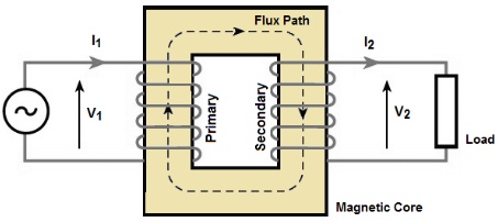
A transformer, in its simplest form, consists essentially of two insulated winding’s interlinked by a common or mutual magnetic field established in a core of magnetic material. When one of the winding’s, termed the primary, is connected to an alternating-voltage source, an alternating flux is produced in the core with an amplitude depending on the primary voltage, frequency and number of turns. This mutual flux links the other winding, called the secondary.
A voltage is induced in this secondary of the same frequency as the primary voltage. But its magnitude depends on the number of secondary turns. When the number of primary and secondary turns are properly proportioned, almost any desired voltage ratio, or ratio of transformation can be achieved. The subscript “1” will be associated with the primary and “2” with the secondary. The reader should note that these are arbitrary terms and in no way affect the inherent properties of a transformer. If the secondary voltage is greater than the primary value, the transformer is called a step-up transformer; if it is less, it is known as a step-down transformer; if primary and secondary voltages are equal, the Transformer Circuit is said to have a one-to-one ratio. One-to-one transformers are used to electrically isolate two parts of a circuit. Any transformer may be used as a step-up or step-down depending on the way it is connected. In order to ensure the largest and most effective magnetic linkage of the two winding’s, the core, which supports them mechanically and conducts their mutual flux, is normally made of highly permeable iron or steel alloy (cold-rolled, grain-oriented sheet steel). Such a transformer is generally called an iron-core transformer.
Transformers operated from 25-400 Hz are invariably of iron-core construction. However, in special cases, the Transformer Magnetic Circuit Model linking the winding’s may be made of nonmagnetic material, in which case the transformer is referred to as an air-core transformer. The air-core transformer is of interest mainly in radio devices and in certain types of measuring and testing instruments. An intermediate type, exemplified by a type of induction coils and by small transformers used in speech circuits of telephone systems, utilizes a straight core made of a bundle of iron wires on which the primary and secondary coils are wound in layers.