Transistor Biasing and Stabilization Articles:
Selection of Operating Point in Transistor Biasing: To study the selection of operating point in Transistor biasing conditions on the performance of a transistor, it is necessary to draw a dc load line on the output characteristics of the transistor. Consider … (Read More)
Bias Stability Factor of Transistor: Only the fixing of a suitable operating point is not sufficient but it is also to be ensured that the operating point remains stable i.e., it does not shift due … (Read More)
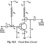
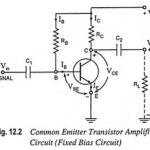
Fixed Bias Circuit Diagram – Advantages and Disadvantages: Fixed Bias Circuit Diagram shown in Fig. 12.5 uses two batteries VBB and VCC. The battery VBB gives potential to the base terminal through resistance RB (of the order of hundred kΩ) and … (Read More)
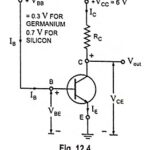
Simple Biasing Circuit Diagram: The simplest biasing circuit diagram could be as shown in Fig. 12.4. The emitter-base junction is forward biased by the battery VBB and the collector-base junction is reverse biased by the battery VCC. The voltage VBE across the … (Read More)
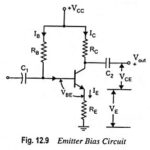
Emitter Bias Circuit Diagram: This Emitter Bias Circuit Diagram is obtained by simply introducing an emitter resistor to the fixed bias circuit as shown in Fig. 12.9. For analysis, we will first examine the base-emitter loop and then use the results … (Read More)
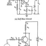
Self Bias or Potential Divider Bias Circuit: This is the most commonly used biasing arrangement. The arrangement of Self Bias or Potential Divider Bias Circuit is shown in Fig. 12.17 (a). The name voltage divider is derived due to the fact … (Read More)
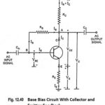
Base Bias with Collector Feedback Circuit: This Base Bias with Collector Feedback Circuit is like a fixed bias circuit except that the base resistor RB is returned to the collector terminal instead of supply VCC. It derives its name from the … (Read More)
Base Bias Circuit With Collector and Emitter Feedback: In this Base Bias Circuit With Collector and Emitter Feedback circuit, as obvious from its name, both collector and emitter feedbacks are used in an attempt to reduce circuit sensitivity to changes in … (Read More)
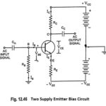
Two Supply Emitter Bias Circuit: From the stability point of view, this two supply emitter bias circuit is the best of all already discussed circuits, but it has one drawback that it requires two power supplies or batteries or it requires … (Read More)
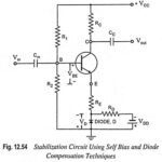
Various Bias Compensation Methods: During the discussion made for various biasing methods for providing stability to the operating point we have seen that self bias (or potential divider bias) and collector-to-base bias circuits provide better operating point stability but in both … (Read More)
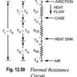
Thermal Resistance – Definition, Circuit Diagram and Equation: With power transistors, a designer often uses a heat sink to get a high power rating for the transistor. As already mentioned, the heat sink allows the internally generated heat to escape more … (Read More)