Two pulse half controlled bridge converter:
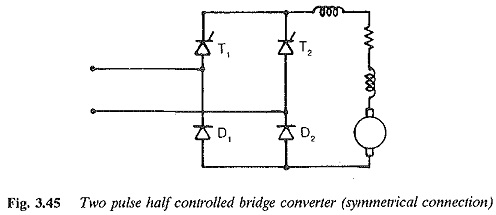
A Two pulse half controlled bridge converter is obtained by connecting a two pulse controlled midpoint converter in series with an uncontrolled one, as shown in Fig. 3.45. The controlled converter has thyristors T1 and T2 in a common cathode connection whereas the uncontrolled one has diodes D1 and D2 in a common anode connection. The former is a positive group and the latter a negative group. The bridge can also be obtained with the uncontrolled converter in the positive group and the controlled one in the negative group.
The voltage of the controlled converter can be varied from positive maximum to negative maximum by changing the phase angle from 0 to 180°. The output voltage of the uncontrolled bridge is constant. The net voltage at the load terminals is the sum of the voltages of the controlled and uncontrolled groups. The average voltage varies from a maximum value to zero. The output voltage cannot reverse its polarity, due to the uncontrolled bridge. Only rectification is possible.
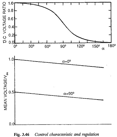
Taking the inverter limit of the controlled group into consideration, the phase angle can be varied from 0 to near about 180°. The average dc voltage varies from a maximum value to near about zero. Because of the inverter limit of the controlled converter, zero voltage is not possible.
The average value of the voltage at the dc terminals is given by
The control characteristic is shown in Fig. 3.46, wherein the inverter limit is indicated.
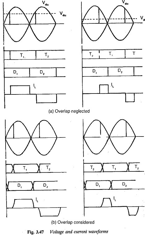
For inductive loads there is an inherent free wheeling action provided by the incoming diode and the reverse biased thyristor, until the incoming thyristor is turned on. Referring to Fig. 3.47, the thyristor T1 and the diode D2 conduct during the positive half cycle while T2 and D1 do so in the next half cycle.
There are also periods of time where T1D1 or T2D2 conduct simultaneously. The load current free wheels and mains are relieved from supplying the current when the devices placed diagonally opposite conduct, the supply voltage appears across the load. The current flows from the supply to the load. When the devices connected in series conduct, the load voltage is zero and the load current free wheels.
To start with let us assume that T1 and D2 are conducting. The portion of the positive half cycle appears across the load (α to π). At ωt = π, D1 gets forward biased and the current transfers from D2 to D1 D2 to T1 continues to conduct till T2 is fired at appropriate firing angle [α + π]. Current transfers from T1 to T2. Now T2 and D1 conduct. The supply voltage appears across the load. Thus the thyristor is in conduction for 180°. There is an inherent free wheeling action because of the diodes, and this makes the voltage across the load zero. The negative excursions of the load voltage are prevented by the uncontrolled bridge.
The output voltage in the working range is affected by the device drops in the forward directions, as well as the resistance drops. The reactances in the line side of the converter are responsible for overlap. The current transfer takes place in a definite amount of time. The rate of change of current combined with the reactances causes a voltage drop. This can be determined in the same way as for a fully controlled converter. Therefore
For Very small firing angles and highly inductive loads, it is not possible to turn off the converter in this connection by a sudden removal of firing pulses. The last thyristor fired remains in conduction indefinitely, making the input voltage appear across the dc terminals every other half cycle. For example, assume that at some instant of time T1 and D2 are conducting and instant the firing pulses are removed. When T1 is reverse biased, the natural free wheeling through T1 and D1 maintains the current in the load and the load voltage is zero. If the current has not decayed to zero during this time, the thyristor T1 gets a forward voltage and conducts as if α = 0. The positive half cycle of voltage appears across the load and the load current flows through T1 and D2 for the complete half cycle. This phenomenon is called half waving. To turn off the converter is to maintain the gate pulses and retard the firing angle such that the load voltage is reduced. Consequently the load current falls below the holding current of the thyristor.
The elimination of the negative excursions of dc voltage due to natural free wheeling is advantageous, in that the superimposed ac ripple on the average dc voltage decreases with reduced smoothing equipment.
It can also be observed from the current waveforms that the period of conduction of the input current pulses decreases as the firing angle is retarded, i.e. output voltage is reduced. Thus the reactive power requirements of a half controlled bridge are considerably less than those of the fully controlled one at reduced voltage. The rms value of the input current
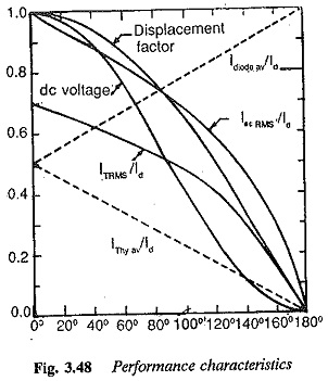
The fundamental displacement factor is cos α/2. The saving in control reactive power is considerable, as the free wheeling action takes place even at α = π. However there is no saving in commutation reactive power.
The periods of current flow in the thyristor and diode are equal. The peak forward or reverse voltage of the devices is equal to![]()
The harmonic components of the input current depend upon the control angle. They have different spectrum at different α. Therefore the value of g depends upon α. The total power factor is
The ripple content in the output voltage is reduced because of the inherent free wheeling action, which prevents the negative excursions of the output voltage. The amount of smoothing inductance in the load circuit is small it is only 57% of the value required with a fully controlled converter. The performance of the converter is summarised in Fig. 3.48.
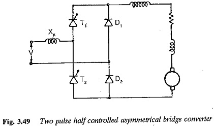
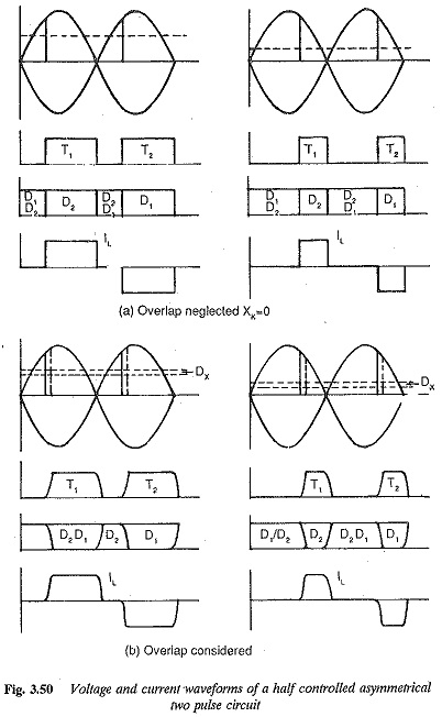
The other possible Two pulse half controlled bridge converter connection is as shown in Fig. 3.49. This is a symmetrical connection. The voltage and current waveforms of the converter are shown in Fig. 3.50.
The free wheeling is provided by the diodes D1 D2. The thyristor T1 and diode D2 conduct in the positive half cycle and T2 and DI in the negative half cycle. At the end of the positive half cycle, D2 acquires a positive voltage and D1 D2 free wheel the load current. This free wheeling prevents the negative portions from appearing in the output voltage. The operation and behaviour of the circuit is the same as the previous circuit as far as the output voltage, power factor, etc. are concerned. However there are two differences. First, the half waving of the circuit is not present. From the waveforms of the current, it can be seen that as a increases the period of conduction of the thyristor decreases and that of the diode increases. The devices can, therefore, be rated accordingly depending upon their maximum period of conduction. The period of the input current pulses decreases as a is delayed.
Applications of Two pulse half controlled bridge converter:
Two pulse half controlled bridge converter of large power find application in tram cars in which single phase power is rectified to feed the traction motor. In these applications one tries to improve the reactive power saving without giving much importance to regenerative braking.
