Types of Arc Control Pots:
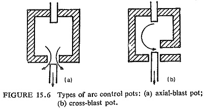
There has been a continuous development in the types of arc control pots, the two basic forms of which are shown in Fig. (15.6). As the arc itself develops the pressure necessary to produce the blast for arc extinction it is to be expected that the pressure will increase as the arc current increases.
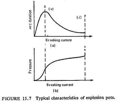
This increased pressure gives a more powerful blast and a greater electrical strength per unit length of arc path, with the result that the restriking voltage transient can be withstood by shorter gaps between moving and stationary contacts. Thus, Arc Control extinction occurs with shorter and shorter arcs as the current increases. Figure (15.7) shows typical characteristics of such a pot. Examination of these curves shows that the limiting rating of a pot can be reached either by the arcing time at the hump X becoming – infinite, i.e. the pot failing to clear, or because the pressure at Y becomes so high that the pot bursts.
For a given pot, the maximum arc duration attained at X is mainly a function of the magnitude and rate of rise of restriking transient voltage whilst the maximum pressure attained at Y is mainly a function of the magnitude of the current and is independent of the restriking transient voltage over a very wide range.
Thus the limiting voltage rating is reached when the pot fails to clear a short-circuit at region X, whilst the limiting breaking-current rating is reached when the pot bursts at Y. The design of high-voltage pots becomes essentially a problem of ensuring that there is sufficient pressure at X to ensure that the arc is positively broken and yet that the pressure at Y is not high enough to burst the pot.
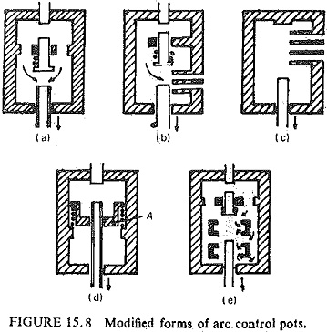
Modified arrangements of pot are shown in Fig. (15.8). In Fig. (15.8a) the arc takes place in two stages: Arc Control first appears in the upper chamber and builds up high pressure: when the spring of the intermediate contact unit is fully extended the lower contact opens in oil already at a high pressure and this, in being forced out down the hollow moving contact sweeps across the arc. The same principle is applied to the cross-jet pot in Fig. (15.8b).
In Fig. (15.8c) the vents are placed immediately adjacent to the stationary contacts, but the pot enclosure continues after the vents cease, forming what is called the compensating chamber. With this arrangement high currents can be extinguished with a minimum travel after contact separation. This also improves the low-current operation, i.e. the current continues to flow until the arc is drawn into the compensating chamber, thus building up the pressure. In other words the arrangement increases the voltage rating at X without decreasing the current rang at Y (Fig. (15.7)).
In Fig. (15.8d) the arc in the upper chamber forces the piston A against the oil in the lower chamber and also forces some oil down the hollow moving contact; as soon as the contact has passed through the piston the pressure in the upper chamber forces the piston down and expels oil from the lower into the upper chamber through the orifice in the piston thereby causing considerable turbulence and rapid deionization.
In Fig. (15.8e) oil is delivered by pressure due to the initial break to several points along the arc path and flow axially with the Arc Control before being discharged.
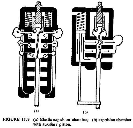
Still in other forms of explosion pots, to avoid explosion at very high currents, pressure limiting valves are used to protect the so called elastic arc chambers; at very low currents. a mechanically driven piston guarantees sufficient flow, (Fig. (15.9)).
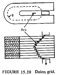
An alternative arrangement is the deign grid shown in Fig. (15.10). The grids surround the arcing contacts and consist of a series of insulating plates made usually of asbestos having interspersed plates of magnetic material, all so disposed and vented that the Arc Control is moved laterally into oil pockets by the electromagnetic force due to the flux in the magnetic grids, where it vaporizes the oil. The resulting gases can only escape by sweeping across the arc path.
