Types of Armature Winding in Electric Machine:
We Know that field and Armature Winding Machine are the essential features of electric machines. The field windings are simple arrangements with concentrated coils (i.e coils in which all the turns have the same magnetic axis). Types of Armature Winding Machine on the other hand comprise a set of coils (single or multiturn) embedded in the slots, uniformly spaced round the armature periphery. The emfs are induced in armature coils due to relative motion between them and the B-wave in the air-gap established by the field windings. In an ac machine (3-phase) the armature coils are symmetrically connected to form a set of three balanced phases (equal emf magnitudes with a relative phase displacement of 2π/3 rad).
In a dc machine the armature coils are connected via commutator segments which are tapped by stationary brushes so as to give a constant (dc) voltage between brushes. It was also seen earlier that when the Armature Winding Machine carries current, it establishes the same number of alternating (north-south) poles for which it is wound.
A coil may be of single-turn having two conductors with end connections or multiturn with two coil-sides each composed of several conductors. The active coil-side (or conductor) length in which the emf is induced equals the armature length (over which the flux density is established). The pitch of a coil is the space angle (electrical) between its two sides and must equal an integral number of slots. The coil pitch may be full (equal to one pole pitch or 180° elect.) or short-pitch (chorded) coils may be used. The pitch of a coil could be expressed in terms of its angular span or in terms of slots. The slots/pole must be an integral number for a full-pitch coil.
Practically there are Two Types of Armature Winding, namely
- Single Layer Winding and
- Two Layer Winding (or Double Layer Winding).
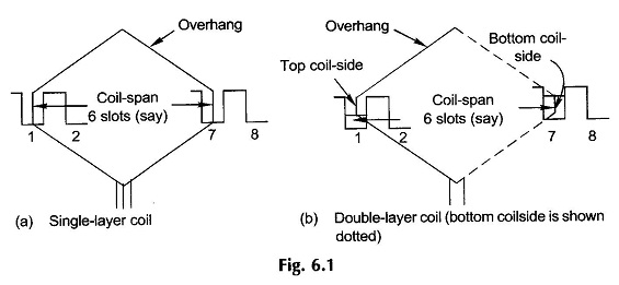
In a Single Layer Winding each coil—side of a coil occupies the whole slot as shown in Fig. 6.1(a). In a Double Layer Winding one coil-side of a coil occupies the upper position in one slot and the second coil-side occupies the lower position in a slot displaced from the first coil-side by the coil-span as shown in Fig. 6.1(b). In a Double Layer Winding each slot is occupied by two coil-sides, one placed on top of the other, referred to as top and bottom coil-sides. It easily follows from Fig. 6.1 that
U= 2 coil-sides/slot (6.1a)
C = S/2 (single-layer winding) (6.1b)
C = S (double-layer winding) (6.1c)
where
- C = number of armature coils
- S = number of armature slots
The primary difference in single- and Double Layer Winding is in the arrangement of the overhang. In Single Layer Winding the coils are arranged in groups and the overhang of one group of coils is made to cross the other appropriately by adjusting the size (corresponding to axial length of armature) and shape of individual coil groups. This means a variety of coils differing both in size and shape resulting in inconvenience and higher cost in production. Single Layer Winding are, therefore, rarely used in modern machine practice except in small sizes. Machines are of course still found in use with Single Layer Windings.
In a Double Layer Winding all the coils are identical in shape and size (diamond shape as shown in Fig. 5.21 is employed) with two coil-sides lying in two different planes. Each slot has one coil-side entering its bottom half from one side and the other coil-side leaving its top half on the other side. A special kink at each end of the diamond shape allows neat symmetrical packing of coil overhangs and the problem of overhang crossing as in a Single Layer Winding is avoided. Because of identical coils, production is facilitated and results in a reduction of cost. DC machine windings are invariably double-layered.
Nomenclature for Types of Armature Winding:
- S = number of slots ( must be divisible by 3 in a 3-phase ac machine)
- C = number of coils
- 2C = number of coil-sides
- Nc = number of turns/coil
- S/P = slots/pole, i.e. pole pitch in terms of slots (is noninteger for fractional slot winding)
- γ = 180∘ P/S slot angle (electrical) or sloth pitch (angular displacement between midpoints of adjacent slots)
- q = number of phases (generally q = 3)
- β = 2π/q, time phase displacement between emfs of successive phases (generally β = 2π/3)
- m = number of slots/pole/phase (SPP)
- A = number of parallel paths
In ac machines it is possible to have only one path or more paths in parallel-phase (each phase is an open-circuit); but dc machine windings are always of closed-circuit type with two or more (even) number of parallel paths.
In large dc machines windings may be arranged with more than one coil-side in top and bottom halves of the slots.
Nomenclature specific to dc machine winding is:
- U = 2C/S, number of coil-sides/slot (even)
- Zs = UNc, number of conductors/slot
- Z = 2CNc, total number of armature conductors
The arrangement of coils round the armature periphery and their interconnections is best illustrated in form of a winding diagram. For the purpose of drawing a Types of Armature Winding diagram, it is convenient to imagine the armature to be laid out flat in a developed form with slots parallel to each other. Slots under the influence of each pole can then be marked out; all coil-sides under one pole will have emfs induced in the same direction with a progressive time phase difference corresponding to the slot angle. Cross-sectional developed view is also handy in illustrating the underlying ideas of ac windings. In a developed form of dc winding, the field poles are also indicated.
