Types of Chimney in Power Plant:
Chimney in Power Plant is used to release flue gas into the atmosphere. The chimney is constructed 2.5 to 3 times of height of the power plant. The main purpose of this is to emit the flue gas at a considerable height to avoid nuisance to the surrounding people.
There are two types of loads acting on the chimney namely
- Its own weight which is considered to act as a single vertical force acting through the centroid
- Wind pressure, which is considered to act as a horizontal force acting on the centroid of vertical projected area. It is found, from the experiments, that the wind pressure acting on a cylinder is 2/3 times of vertical plane surface of same projected area and shape. For design considerations, the wind pressure on the chimney, is taken as 1.5 kN/m2
Three different types of Chimney in Power Plant and their design considerations are given below.
1. Steel Chimney
This type of chimney is preferred for short exhaust stacks where the draft is created by fan. To increase the life of the chimney, these are lined with bricks. The erection period of this type of Chimney in Power Plant is less compared to that of other types. This type of chimney is constructed by welded section and erected by horizontal welding joints (or) by riveting.
Because of low capital cost of the chimney, the number of steel chimney constructed were increased considerably, But the sulphur content in the flue gas created severe problems such as acid condensation and severe attack inside surface of brick, concrete and steel chimneys. This has been rectified by the insulation of the steel chimneys by aluminium cladding.
‘Cold air inversion’ is being faced by the system when several number of boilers are attached to a single chimney. In order to avoid this nowadays, ‘One boiler – One chimney pattern’ is used.
The chimneys in the gas turbine power plants often face the thermal shock brought by an increase in temperature of about 450 – 500°C during a period of full load. The steel chimneys are capable of handling this because of thin wall and high coefficient of expansion of steel.
2. Site constructed chimneys
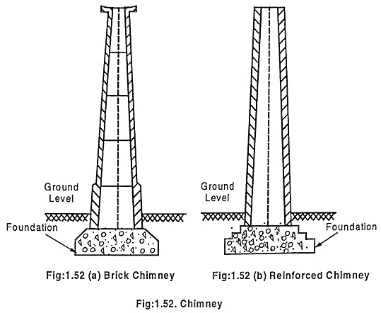
Site constructed chimneys of brick (or) concrete are used where very tall chimneys are necessary for power stations (or) where the life requirement is more than 30 years.
Nowadays perforated radial bricks are used, instead of common bricks, as they give better results. The perforations aid the structural stability. The crushing strength of perforated radial brick is more than that of the design value required in the actual practice.
Another common material that is used for building chimneys is pre-casted reinforced concrete. Due to structural difficulties, it is limited to chimneys of height around 80m. There are two methods 1. “Jump forming” where the shuttering is moved up the stack in steps (or) “Slip forming” where the shuttering is gradually moved up with continuous concrete pouring. The second method is the fastest method of construction. Concrete is not suitable for chimneys due to its high thermal inertia which leads to cracking. The steel chimneys are preferred where the cost factor is important and concrete chimney is preferred where the life of the chimney is most important.
3. Plastic chimneys
These Chimney in Power Plant are made of glass fiber reinforced plastic. They cannot be operated at high temperature. Because at high temperature, the flue gas catches fire and leads to disintegration of chimney. This kind of chimneys plays a vital role where a low stress, low temperature chimney is required for highly corrosive effluents.
Chimney height calculation:
Let
H – height of chimney above grate level in meters
W – weight of air required in kg per kg of fuel
Tg – Average absolute temperature of chimney gases in K
Ta – Absolute temperature of air outside the chimney in K
Weight of chimney gases produced = w kg of fuel burnt
Volume of chimney gases at 273 K = volume of 1 kg of air at 273 K
Therefore, volume of 1kg of air at Ta
Volume for W kg of air at Ta
Density of air at
Therefore, Pressure at grate due to column of cool air of H meters height = Density x height of chimney
Similarly,
Volume of chimney gases at Tg per kg of air
Volume of (W + 1) kg of chimney gases at Tg
Density of chimney gases at Tg
Therefore, pressure at the grate by column of hot gases of height H meter = Density x H kg/m2
Therefore, Pressure P causing the draught = pressure due to column of cool air – pressure due to column of hot air
If draught is measured in h mm of water by U-tube manometer, then
[Therefore 1 kg/m2 = 1 mm of water column]
Let h’ be the height of column of hot gases then


