Types of Encoders in Digital Electronics:
By the use of a digital code, it is possible to identify the position of a movable test piece in terms of a binary number. The position is converted into a train of pulses. This is achieved by a digital transducer and is also termed as encoder. Since the binary system uses only two states, 0 or 1, it can be easily represented by two different Types of Encoders in Digital Electronics systems, namely
- Optical Encoder
- Resistive Electric Encoder
- Shaft Encoder
Digital transducers using optical methods are called Optical Encoders, while those using electrical methods are called Resistive Electrical Encoders.
1. Optical Encoder:
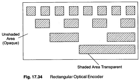
A sector may be designed as shown in Fig. 17.34, with a pattern of opaque and translucent areas. A photo sensor and a light source is placed on the two sides of the sector. The displacement is applied to the sector and therefore changes the amount of light falling on the photo electric sensor. The pattern of the illuminated sensor then carries the information to the location of the sector.
Figure 17.34 shows a possible pattern on sector of opaque and translucent areas. The number of levels in the encoder determines the accuracy with which the device operates.
Advantages:
- They give a true digital readout
- No mechanical contact is involved and therefore problems of wear and tear and alignment are not present
Disadvantages:
- Light sources burn out. (However, the life of the light is about 50,000 hours.)
2. Resistive Electric Encoder:
Another Types of Encoders in Digital Electronics in which a pattern may be used is the resistive electric encoder. The shaded areas are made of conducting material and the unshaded areas of insulating material. Sliding contacts are used for making the contacts. Circuits of the sliding contacts which come in contact with the conducting areas are completed, while those which make contact with insulated areas are not completed. The encoder gives a digital readout which is an indication of the position of the device, and hence determines the displacement.
Advantages:
- It is relatively inexpensive.
- It can be made to any degree of accuracy desired, provided the sector is made large enough to accumulate the required number of rows for binary The sectors are quite adequate for a slowly moving system.
Disadvantages:
- Wear and tear of the contacts causes error.
- There is often an ambiguity of 1 digit in LSB
3. Shaft Encoder:
A spatial encoder is a mechanical converter that translates the angular position of a shaft into a digital number. It is therefore an A/D converter.
An increasing number of measuring instruments are being used to communicate with digital computers for measurement and control applications. There are two ways of generating digital signals. The first converts the analog variable to a shaft rotation (or translation in linear measurements) and then uses many types of shaft angle encoders to generate digital voltage signals.
The other form converts the analog variable into an electrical analog signal and then converts this into digital form. These two forms are very close to a true digital transducers.
To understand the operation of a shaft encoder, let us consider a translational encoder (a linear displacement transducer) shown in Fig. 17.34. The encoder shown has four tracks (bits) and is divided into conducting and insulating positions, with a smallest increment of 0.01 mm. As the scale moves under the brushes, the lamp circuits are made or broken, so that the number shown on the readout lamps is at every instant equal to one hundredth mm.
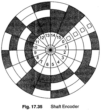
For angular displacements, the pattern given in Fig. 17.34 is changed or modified, so that the length of the scale becomes the circumference of a circle on a flat disc. The brushes are then placed along a radial line on the disc, as shown in Fig. 17.35.
The disc is divided into concentric circular tracks, each of which is then divided into segments in a manner depending upon the code being used.
For pure binary code, the inner most track is halved, the next quartered, the next divided into eight parts, and so on. Each track has twice as many segments as the adjacent one near the centre. The detection method determines the treatment of the disc. Alternate segments on each track are made transparent and opaque, if transmitted light and photo cells are used. If the segments are made reflecting and non-reflecting, reflected lights and photo cells are used. Electrical methods are used for detection in case the segments are made alternately conducting and non-conducting.
The accuracy in this Types of Encoders in Digital Electronics depends upon on the number of tracks used and if there are n tracks, the accuracy obtained is 360°/2n.
Such discs are manufactured with diameters ranging from 5 — 25 cm and give unique codes for 100 — 50,000 positions per 360°. The sequence and order of indications represent the position of the shaft in the coded form.

