Types of Rotating Electric Machine:
The Types of Rotating Electric Machine are namely
- the dc machine,
- the polyphase synchronous machine (ac), and
- the polyphase induction machine (ac).
Three materials are mainly used in machine manufacture; steel to conduct magnetic flux, copper (or aluminium) to conduct electric current and insulation to insulate the voltage induced in conductors confining currents to them.
Types of Rotating Electric Machine comprise of two parts: the cylindrical rotating member called the rotor and the annular stationary member called the stator with the intervening air-gap as illustrated in Fig. 1.4. The rotor has an axial shaft which is carried on bearings at each end located in end covers bolted to the stator. The shaft extends out of the end cover usually at one end and is coupled to either the prime mover or the load.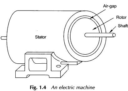 The stator and rotor are both made of magnetic material (steel) which conducts the magnetic flux upon which depends the process of energy conversion. In both dc and synchronous machines, the main field is created by field poles excited with direct current. The winding on the field poles is called the field winding. The relative motion of the field past a second winding located in the other member induces emf in it. The winding interchanges current with the external electric system depending upon the circuit conditions. It is this winding, called the armature winding, which handles the load power of the machine, while the field winding consumes a small percentage (0.5% to 2%) of the rated load power. The load dependent armature current is known as load current.
In a dc machine the field poles are on the stator while the rotor is the armature as shown in the cross-sectional view of Fig. 1.5. The field poles are symmetrical and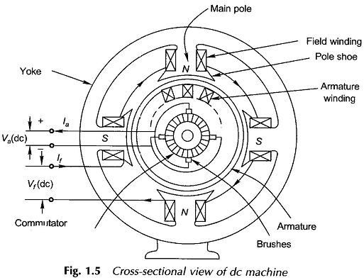 are even in number, alternately north and south. As the armature rotates, alternating emf and current induced in the armature winding are rectified to dc form by a rotating mechanical switch called the commutator, which is tapped by means of stationary carbon brushes. The commutator is cylindrical in shape and comprises several wedge-shaped copper segments bound together while they are insulated from each other. The armature is made of laminated steel with slots cut out on the periphery to accommodate the insulated armature winding. The ends of each armature coil are connected to the commutator segments to form a closed winding. The armature when carrying current produces stationary poles (same as number of field poles) which interact with the field poles to produce the electromagnetic torque.
In a synchronous machine the field poles could be either on the stator or rotor, but in all practical Electric Machine the rotor carries the field poles as shown in the cross-sectional view of Fig. 1.6. The field poles are excited by direct current. The stator forms the armature carrying a 3-phase winding wound for the same number of poles as the rotor. All the three phases have identical windings with the same angular displacement between any pair of phases. When the rotor rotates, it produces alternating emf in each phase forming a balanced set with frequency given by
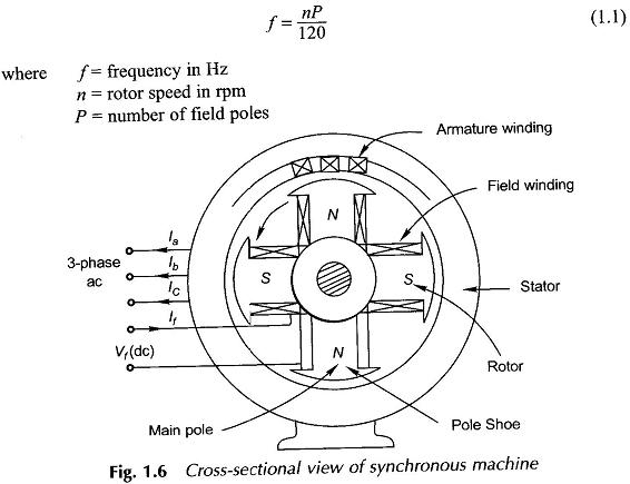 For a given number of poles, there is a fixed correspondence between the rotor speed and the stator frequency; the rotor speed is therefore called the synchronous speed. When balanced 3-phase currents are allowed to flow in the armature winding, these produce a synchronously rotating field, stationary with respect to the rotor field as a result of which the Electric Machine produces torque of electromagnetic origin. The synchronous motor is, however, nonselfstarting.
In both dc and synchronous machines the power handling capacity is determined by the voltage and current of the armature winding, while the field is excited from low power dc. Thus these Electric Machine types are doubly excited. Quite different from these, an induction machine is singly excited from 3-phase mains on the stator side. The stator winding must therefore carry both load current and field-producing excitation current. The stator winding is 3-phase, similar to the armature winding of a synchronous machine. When excited it produces a synchronously rotating field. Two types of rotor constructions are employed which distinguish the type of induction motor.
1.Squirrel-cage Motor:
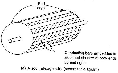
Here the rotor has copper (or aluminium) bars embedded in slots which are short-circuited at each end as shown in Fig. 1.7(a). It is a rugged economical construction but develops low starting torque.
2. Slip-ring (or wound-rotor) Motor:
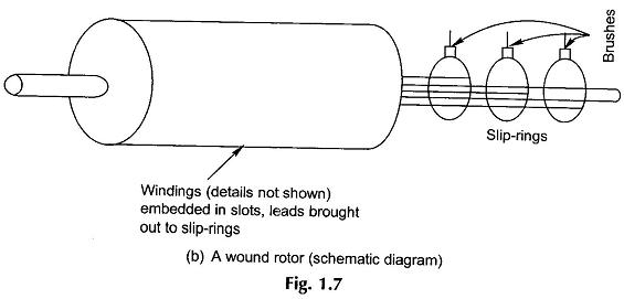
The rotor has a proper 3-phase winding with three leads brought out through slip-rings and brushes as shown in Fig. 1.7(b). These leads are normally short-circuited when the motor is running. Resistances are introduced in the rotor circuit via the slip-rings at the time of starting to improve the starting torque.
The rotating field created by the stator winding moves past the shorted rotor conductors inducing currents in the latter. These induced currents produce their own field which rotates at the same speed (synchronous) with respect to the stator as the stator-produced field. Torque is developed by the interaction of these two relatively stationary fields. The rotor runs at a speed close to synchronous but always slightly lower than it. At the synchronous speed no torque can be developed as zero relative speed between the stator field and the rotor implies no induced rotor currents and therefore no torque.
Single-phase ac motors are employed for low-voltage, low-power applications fractional-kW motors. They operate on the same basic principles as the 3-phase motor, but the pulsating single-phase field produces additional losses, reducing motor torque and the pulsating torque component increases the noise level of the types of Motor.
An induction machine connected to the mains when driven at supersynchronous speed behaves as a generator feeding power into the electric system. It is used in hydroelectric stations and aerospace applications.
The insulation of a Electric Machine (or transformer) is its most vulnerable part because it cannot be stressed beyond a certain temperature. For a given frame size, the steady temperature rise is determined by the machine loading, the associated power loss (this appears in the form of heat) and the cooling provided. Thus the maximum machine loading called its rating for a given frame size is limited by the permissible temperature rise which is dependent upon the class of insulation used. In the case of high-speed dc machines poor commutation (reversal of current in armature coils) may become a limiting factor even before the temperature limit is reached. The speed itself may be a limiting factor in very high-speed machines on account of the centrifugal forces developed. This limit is more stringent in dc machines with complicated armature construction than in the rugged rotor induction motor. Because of their high thermal capacity, machines are quite capable of withstanding a fair amount of overloads for short durations.
Motor Control:
There is great diversity and variety in the components and systems used to control rotating machines. The purpose of a motor control may be as simple as start/stop or the control of one or more of the motor output parameters, i.e. shaft speed, angular position, acceleration, shaft torque and mechanical power output. With the rapid development of solid-state power devices, integrated circuits and cheap computer modules, the range, quality and accuracy of electronic motor control has become almost infinite. Electric Machines and other electromechanical systems having the highest possible precision and reliability have been developed for nuclear power and space applications. Using solid-state power converters, schemes have been devised to start, stop or reverse dc motors in the megawatt range in a matter of seconds. Finally, as the nonconventional and renewable sources of energy, such as solar, windmill, etc., would become economical, viable electromechanical energy converters will be required with matching characteristics.
Economic and Other Considerations in Electric Machines Types:
As in other devices, economics is an important consideration in the choice of Types of Rotating Electric Machine and the associated control gear. The trade-off between the initial capital investment and the operating and maintenance cost must be taken into account in this choice; the decision may be in favor of a high-efficiency high-cost motor, particularly in an environment of rising energy costs. While the transformer produces magnetic noise, the rotating machines, in addition, produce mechanical noise arising from bearings, windage, etc. In present-day noise-pollution levels, the noise figure in decibels can be an important factor in Types of Motor choice. Theses considerations are not the subject matter of this book which emphasises electromechanical principles and the theory and application of Electric Machines Types including transformers.
