Uniform Field Electrode Gaps:
Sphere gaps, although widely used for voltage measurements, have only limited range with Uniform Field Electrode Gaps. Hence, it is not possible to ensure that the sparking always takes place along the uniform field region. Rogowski presented a design for Uniform Field Electrode Gaps for sparkover voltages up to 600 kV. The sparkover voltage in a uniform field gap is given by![]()
where A and B are constant, S is the gap spacing in cm, and V is the sparkover voltage.
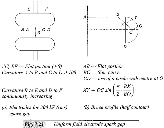
Typical uniform field electrodes are shown in Fig. 7.22. The constants A and B were found to be 24.4 and 7.50 respectively at a temperature T = 25°C and pressure = 760 torr. Since the sparking potential is a function of air density, the sparkover voltage for any given air density factor d (see Eq. 7.22) is modified as
Bruce made uniform field electrodes with a sine curve in the end region. According to Bruce, the electrodes with diameters of 4.5, 9.0, and 15.0 in can be used for maximum voltages of 140, 280, and 420 kV respectively. For the Bruce profile, the constants A and B are respectively 24.22 and 6.08. Later, it was found that with humidity the sparkover voltages increases
where,
V = sparkover voltage, kVpeak(in kVd.c.),
e = vapour pressure of water in air (mm Hg).
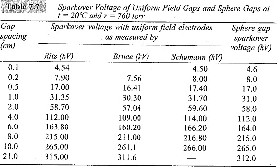
The constants A and B differ for a.c., d.c., and impulse voltages. A comparison between the sparkover voltages (in air at a temperature of 20°C and a pressure of 760 torr) of a uniform field electrode gap and a sphere gap is given in Table 7.7. From this table it may be concluded that within the specified limitations and error limits, there is no significant difference among the sparkover voltages of sphere gaps and uniform field gaps.
The sparkover voltage of uniform field electrode gaps can also be found from calculations. However, no such calculation is available for sphere gaps. In spite of the superior performance and accuracy, the uniform field spark gap is not usually used for measurement purposes, as very accurate finish of the electrode surfaces and careful alignment are difficult to obtain in practice.
Rod Gaps:
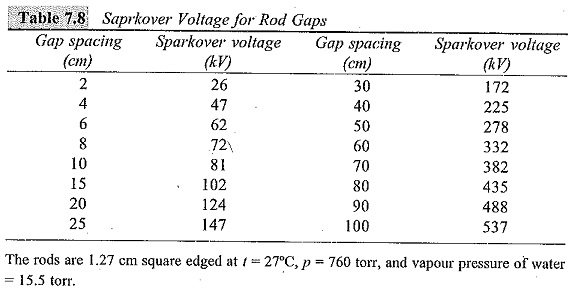
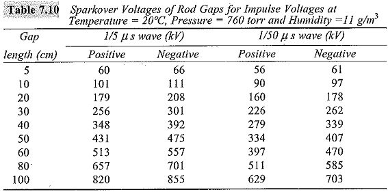
A rod gap is also sometimes used for approximate measurement of peak values of power frequency voltages and impulse voltages. IEEE recognize that this method gives an accuracy within ± 8%. The rods will be either square edged or circular in cross-section. The length of the rods may be 15 to 75 cm and the spacing varies from 2 to 200 cm. The sparkover voltage, as in other gaps, is affected by humidity and air density. The power frequency breakdown voltage for 1.27 cm square rods in air at 27°C and at a pressure of 760 torr with the vapour pressure of water of 15.5 ton is given in Table 7.8. The humidity correction is given in Table 7.9. The air density correction factor can be taken from Table 7.6.
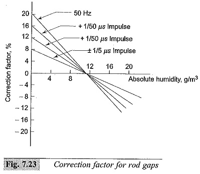
In case of impulse voltage measurements, the IEC and IEEE recommend horizontal mounting of rod gaps on insulators at a height of 1.5 to 2.0 times the gap spacing above the ground. One of the rods is usually earthed. For 50% flashover voltages, the procedure followed is the same as that for sphere gaps. Corrections for humidity for 1/5 μs impulse and 1/5 μs impulse waves of either polarity are given in Fig. 7.23. The sparkover voltages for impulse waves are given in Table 7.10.
