Vacuum Circuit Breaker:
Although the advantages of interrupting the arc in a vacuum were recognized as early as the nineteenth century, this did not find wide application till a few years ago. This was because the knowledge of problems in material science, vacuum technology and plasma physics was not sufficiently advanced to provide solution to the many technological problems encountered in the design and construction of a reliable Vacuum Circuit Breaker.
High vacuum has two outstanding properties: (1) the highest insulating strength known, and (2) when an a, c. circuit is opened by the separation of contacts in a vacuum, interruption occurs at the first current zero with the dielectric strength across the contacts building up at a rate thousands of times higher than that obtained with conventional circuit breakers. These properties obviously make the Vacuum Circuit Breaker more efficient, less bulky and cheaper. The service life also is much greater than that of conventional equipment and hardly any maintenance is necessary. Vacuum breakers are ideally suited for most duties encountered in typical electric utility and industrial applications. Their voltage and interrupting rating is such that with little modifications, they may be made to perform specific switching duties on high-voltage a. c. systems. Field experience has proved the unique performance and reliability characteristic of vacuum devices.
The Vacuum Medium:
Every medium that has a pressure below atmospheric (760 mm of mercury) is known as vacuum. Torricelli is known to be the first man who succeeded in evacuating a space by building his mercury barometer. Low pressures are measured in terms of torr, where 1 torr=1 mm of mercury. Now with various improved techniques pressures as low as 10-7 torr can be achieved.
The value of the pressure of the medium has a marked effect on the molecular structure of the medium. In the high pressure ranges of vacuum system the mean free path is very small and the molecules are in a constant state of inter-collision, the gas behaves as a fluid and is known to be in a state of viscous flow. As the pressure is reduced the mean free path increases. Eventually a point is reached at which the mean free path is equal to or greater than the dimensions of the confining chamber. Under this condition the molecules will collide more frequently with the walls of the chamber than with each other. In this region the gas is said to be in a state of molecular flow.
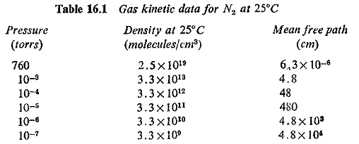
The division between the two regions is specified by a dimensionless parameter called the Knudsen number. For a cylindrical tube the Knudsen number is defined as the ratio of the mean free path (Lm) of the gas molecules to the radius (R). When Lm/R is less than 0.01 gas flow is viscous; if the ratio is greater than 1, the flow is molecular. The range between these two limits is called the transition range. Table 16.1 shows the value of mean free path for N2 at various values of pressure. The gaseous medium in vacuum interruption devices is usually in the molecular flow range.
The Vacuum Arc:
When contact separation takes place in air the ionized molecules are probably the main carriers of electric charges and responsible for low breakdown value. In vacuum arc the neutral atoms, ions and electrons must ultimately come from the electrodes themselves, and not from the medium in which the arc is drawn. As the current carrying contacts are parted, the current concentrates at a few local high spots on the contact surfaces. Normal conduction through metal ceases when the last bridge between the two contacts is vaporized. The phenomena at the active spots on the electrodes of a Vacuum Circuit Breaker are similar to those of conventional high pressure arcs where the current density is in the range of 105-106 amps/cm2. In vacuum arc the emission occurs only at the cathode spots and not from the entire surface of the cathode. For this reason the vacuum arc is also known as the cold cathode arc.
In fact the emission of electrons and ions from the cathode spots may be due to any or the combination of the following mechanisms:
- Thermionic emission.
- Field emission.
- Thermionic and field (TF) emission.
- Secondary emission resulting from positive ion bombardment.
- Secondary emission by photons.
- Pinch effect emission.
At high currents the ionized metal vapour spreads through quite a large volume surrounding the electrodes. At lower currents the quantity of vapour produced is greatly reduced. Since the vapour evolved from the cathode spots expands rapidly in vacuum, the probability of maintaining a charge carrier density sufficient to retain adequate conductivity in the column and sustain the emission process becomes increasingly small. At current zero the cathode spots extinguish in times of the order of 10-2 second.
Vacuum Arc Stability:
In a 50 Hz a.c. network the current decreases to zero once every 10 ms. If the circuit is interrupted at a zero current point no overvoltage will result. Hence for a successful interruption it is necessary that the arc be stable for a half-cycle duration and particularly that it continues to exist at currents approaching zero. It has been found that the arc stability depends on (I) the contact material and its vapour pressure and (2) circuit parameters such as voltage, current, capacitance and inductance. In low current circuits most of the evaporation takes place at discrete points known as cathode spots; at higher currents the gas evaporates from cathode and anode spots. In addition to these sources gas is added to the contacts enclosure when it is stripped from other parts of the enclosure because of high temperature and impinging metal vapour.
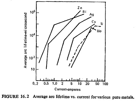
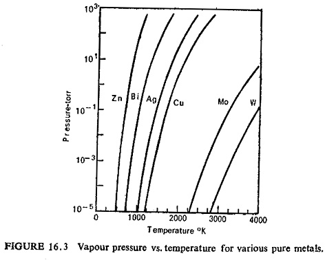
It was shown that vapour pressure and arc stability are interrelated. The higher the vapour pressure at lower temperatures, the longer the life time of the arc. Figure (16.2) shows average arc lifetime for some pure metals, and Fig. (16.3) shows relationship between pressure and temperature for various metals.
Shunting the contacts with different values of capacitance demonstrates that the larger the capacitance the lower the average lifetime of the arc. Adding a large inductance in series with Cu—Bi contacts results in an increase of the arc duration. The chopping level depends upon the vapour pressure and the thermal conductivity of the cathode material. A good heat conductor will cool very rapidly and its contact surface temperature will fall. This will reduce the evaporation rate and the arc will be chopped because of insufficient vapour. On the other hand a bad heat conductor will maintain its temperature and vaporization for a longer time and the arc will be more stable.
Vacuum Breakdown:
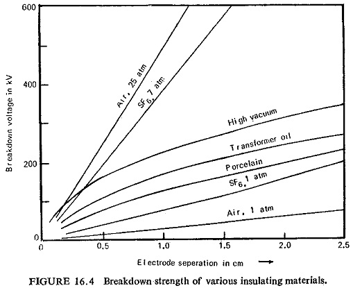
The major insulating media are atmospheric air, oil, paper and porcelain. These can withstand appreciable voltage but they are minute as compared to the withstand voltage of a gap in vacuum. Figure (16.4) illustrates the breakdown strength of various insulating materials.
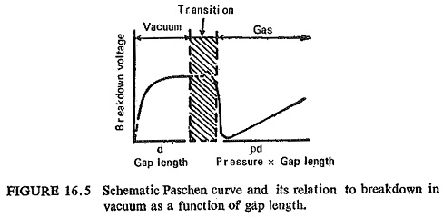
Typically the voltage a gap can withstand decreases with reduced pressure (actually density) to a minimum and then begins to rise rapidly with further reduction of ambient gas density. This is illustrated in Fig. (16.5), which shows an idealized Paschen Curve where breakdown voltage is plotted as a function of pressure times gap length.
When pressure is reduced below the point where the mean free path of the residual gas molecules is of the order of the tube dimensions, approximately 1 micron in many practical cases, the breakdown voltage ceases to depend upon the gas within vessel and is influenced most strongly by composition, condition and arrangement of the electrode surfaces and walls of the tube. This transitional range is shown shaded in the Fig. (16.5). Below the transitional range it is high vacuum of the order of 10-4-10-6 torr and the mean free path of the residual gas molecules becomes very large compared to the gap between the electrodes (see Table 16.1). In a gap of 1 cm only a few electrons in a million get to collide with molecules and form ions. It is this fact which is responsible for the very high breakdown strength of vacuum. In this range the breakdown strength is independent of the gas density, but varies with gap length only. Hence the breakdown strength is plotted against gap length only in this region.
Vacuum breakdown initiation like the vacuum arc must depend upon products evolved under the action of high fields from the electrodes and walls which are bombarded by field emitted electrons, rather than upon the medium in which the electrodes are immersed.
The actual value of breakdown voltage for a given gap depends quite strongly upon the condition of the electrode surfaces. Highly polished and thoroughly degassed electrodes have shown particularly high breakdown voltages. Contacts get roughened after arcing and thus the breakdown strength decreases. Generally improvement in breakdown strength after arcing can be obtained by applying successive high voltage impulse sparks. This does not alter the arc roughened surfaces to any noticeable degree but probably does remove loosely adhering metal particles from the electrodes deposited there by the vapour blast during arcing.
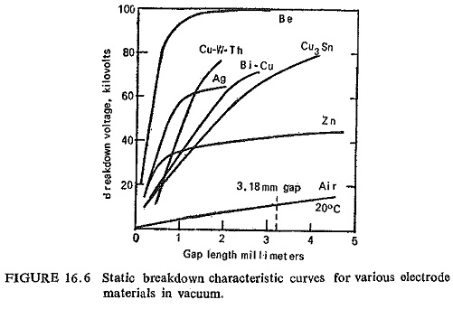
Figure (16.6) shows the average static breakdown voltage vs. gap length for several rough surface of electrode material in a vacuum of the order of 10-6 torr. Similar breakdown data for N2 (air) are shown for comparison. Most of the materials shown here gain much of their ultimate breakdown strength in less than 3 mm gap for the particular geometry shown. Such a characteristic permits the use of short gaps in vacuum switches which results in simplifying the operating mechanism and in increasing the speed of operation over conventional switches.
Current Chopping:
As the current falls, the arc tends to extinguish at a finite current level whose value depends on the vapour pressure and the electron emission characteristics of the contact material, unlike in oil or air-blast circuit breakers where it is generally agreed that the current chopping arises from an instability in the are column. Chopping leads to excessive overvoltages endangering the system insulation and causing reignition of the arc. It is desirable to dissipate energy in the arc itself and from this, point of view, reignition occurring after chopping is welcome. Basically, however, chopping should be avoided. It is possible to reduce the current level at which chopping occurs by choosing a contact material which gives out sufficient metal vapour to allow the current to come to a very low value or zero value, but this is rarely done since it is likely to affect other properties notably the dielectric strength.
Recovery Characteristics of Vacuum Devices:
It has already been stated that high vacuum possesses extremely high dielectric strength. At current zero the cathode spot extinguishes within 10-8 second and after this the original dielectric strength is established. This quick return of high dielectric strength is, of course, due to the fact that the vaporized metal which is localized between the contacts, diffuses rapidly due to the absence of gas molecules. The metal molecules are blown at high speeds to the glass walls and condense there.
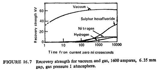
The rate of dielectric recovery of a vacuum gap in first few microseconds after arc interruption is approximately 1 KV/μ. sec for an arc current of 100 A, as compared with 50 V/μ sec in the case of air gap. Figure (16.7) shows rates of recovery of different gases and of vacuum. The gases are at atmospheric pressure and current is 1600 A with an open gap distance of 6.35 mm.
Because of the above-mentioned attributes of vacuum interrupters, Vacuum Circuit Breaker can be used without reservations for fault clearing in any location on a system. They can handle the severe recovery transients associated with short line faults or faults close to a transformer without difficulty. All forms of load switching can be performed with the same ease.
Contact Materials:
The preceding considerations reveal that the most important part in a Vacuum Circuit Breaker is the selection of contact material. The desirable properties of a Vacuum Circuit Breaker contact material can be enumerated as follows.
- Good electrical conductivity to pass normal load currents without
- Good thermal conductivity to dissipate rapidly the large heat generated during arcing.
- High cold and hot hardness to prevent wear and tear during normal opening and closing operations.
- High density.
- Sufficiently low vapour pressure to reduce the amount of inseparable metal vapour in the chamber.
- The heat of Vaporization should be such that (i) arc energy generates enough metal vapour to sustain arcing till the first natural current zero, and (ii) there is insufficient vapour present to cause reignition after first current zero.
- High thermoinic function to enable early arc extinction.
- Resistance to welding together.
- High boiling point to reduce arc erosion. High boiling point means high heat of vaporization and greater dissipation of arc energy in vaporizing the material at the cathode spot.
- The material should preferably not have a surface film. If the film cannot be avoided then it should be conducting.
- Low gas content. Gas content of the material should be one part in 107 or lesser to ensure longer service life.
- Sufficient mechanical strength to retain structural integrity under high voltage gradients at the surface.
The most essential requirement of contact material is that it gives out low pressure vapour at the time of arcing. Whereas low vapour pressure metals are better from the arc extinction points of view, the high vapour pressure and low conductivity metals seem to be more desirable to limit the unfavorable consequences due to current chopping.
In view of the multiplicity of requirements that a vacuum switch contact material must meet and in view of the wide range of metals now available, one may say that there is no single metal which combines all the conflicting properties listed above. Metals with good thermal and electrical conductivities invariably have low melting and boiling points, high vapour pressure at high temperature, low electron functions and are considerably soft.
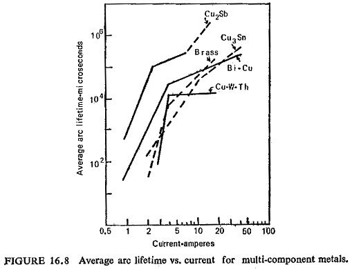
Materials which have high melting and boiling points have low vapour pressures at high temperatures, but are poor conductors. Therefore to combine these contradictory properties in one single material composites of two or more metals or a metal and a nonmetal have to be made. Copper-bismuth, copper-lead, copper-tellurium, copper-thallium, silver-bismuth, silver-lead, and silver-tellurium are some of the examples. Figure (16.8) shows the characteristics of some of these metals.
The commercially produced metals have traces of other elements and trapped gases in them. Once a circuit breaker is sealed it is not possible to take out the gaseous products released during repeated operations, because this will destroy the vacuum of the switch. Moreover the characteristics like breakdown voltage and rate of recovery are affected by the presence of gases. Methods have been evolved to degas metals which are commonly used in electrical and electronic industries. Gas free metals are prepared by vacuum melting in induction furnaces and subsequently deoxidized with sulphur or carbon.
Vacuum Switch Construction:
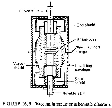
The Vacuum Circuit Breaker is a very simple device as compared to the oil or air-blast circuit breakers. Two contacts are mounted inside an insulating vacuum sealed container. One is fixed and the other may be moved through a short distance. A metallic shield surrounds the contacts and protects the insulating container. A typical assembly of vacuum switch is shown in Fig. (16.9). It consists of two sub-assemblies: (a) the vacuum chamber, and (b) the operating mechanism.
(a) Vacuum Chamber: It is made of synthetic material such as urathane foam which is enclosed in an outer glass fibre reinforced plastic tube or of simple glass or porcelain, two contacts, a metal shield and a metal bellows are sealed inside the chamber. For reasons already mentioned the contacts must be pure and thoroughly degassed.
The metallic bellows, generally made of stainless steel is used to move the lower contact and provides a gap of the order of 5 to 10 mm depending upon the application of the switch. The design of the bellows is of particular significance because the life of the switch depends upon the ability of this part to perform repeated operations satisfactorily
One end of the fixed contact is brought out of the chamber to which the external connection can be made. Similarly provision is made with the lower contact also for external connections but it is firmly joined to the operating rod of the mechanism.
(b) Operating Mechanism: The lower end is fixed to a spring operated or solenoid operated mechanism, so that the metallic bellows inside the chamber are moved upward and downward during closing and opening operations respectively. The contact movement should be such as to avoid bounce. However there should be sufficient pressure to allow a reasonable wipe for a good connection between the two contacts.
Application of Vacuum Switches:
These have promising application to the high voltage switchgear held, specifically where requirements are for a low cost switch having low fault interrupting capacity, but capable of large number of load switching operations without maintenance and in some applications, capable of interrupting line charging or capacitor current without restrike. If the cost is low such switchgear would be ideal for controlling high voltage shunt capacitor banks at small substations or in large substations where fault interruption can be handled by other switchgear. These are very high speed making switches and can be used for many industrial applications.
For a country like India, with 11 to 33KV network extending into vast rural complex, a Vacuum Circuit Breaker should prove a definite advantage. Even with limited MVA rating of say 60 to 100 MVA, it should be suitable for a majority of applications in rural areas.
