Vector Control of Induction Motor:
The sole idea behind the vector control of induction motor is to have an electrical drive which must offer superior performance than widely used separately excited dc motor in industry. Further such a drive should also emerge as a robust, reliable, maintenance free and cheaper alternative of dc drive. Few years back, separately excited dc motor has been considered as a main work horse in the industry. This is due to its faster dynamic performance as compared to the induction motor. The faster dynamic response of the dc motor lies into its being a doubly fed motor along with inherent facility of independent control of torque and flux in the motor. Before the introduction of the vector control of induction motor, the methods which enjoyed wide acceptability in controlling the speed of the cage induction motor drive are termed as voltage control, frequency control, rotor resistance control, v/f control, flux control, slip control, slip power recovery control, etc. All these control methods are termed as scalar control of an induction motor and with these the cage motor exhibits inferior dynamic performance as compared to the separately excited de motor. In their efforts to have a maintenance free, robust and high performance ac drive, the researcher wanted to realize separately excited dc motor performance and characteristics with an induction motor with cage rotor. In this direction, Blaschke has introduced the concept of Vector Control of Induction Motor. Blaschke, in 1972 has introduced the principle of field orientation to realize dc motor characteristics in an induction motor drive. For the same, he has used decoupled control of torque and flux in the motor and given its name as transvector control.
The cage induction motor drive with vector or field oriented control offers a high level of dynamic performance and the closed-loop control associated with this drive provides the long-term stability of the system. Despite there being no major difference between scalar and vector controls, the latter has some properties which make it favorable as a control system with high dynamic performance. The vector control is also called as an independent or decoupled control wherein the torque and flux current vectors are controlled.
It is a well established fact that in the vector control mode the cage motor drive is linearized and it behaves like a fully compensated separately excited dc motor, wherein the control of armature current directly affects the electromagnetic torque developed by the drive. Similarly, in cage motor the vector control method, the two currents in quadrature responsible for flux and torque production, respectively, are controlled independently and the response of the torque producing component of current is very fast thereby providing a quicker control of the torque and hence the drive exhibits a high level of dynamic performance.
In a broad sense, control of cage induction motor such that it behaves like a fully compensated separately excited dc motor, is known as its vector. In this case, the stator currents are expressed with reference to a frame of co-ordinates which rotates in synchronism either with the stator or rotor mmf vector. Stator currents expressed on these co-ordinates are resolved into two orthogonal components which produce the flux and torque in the motor. These are similar to the dc motor in which torque and flux are controlled by controlling armature and field currents independently.
To control the torque and flux (thereby speed) independently in the induction motor, there is need to control the magnitude and phase of the three stator currents (ias, ibs , ics) through a fast inverter. For this purpose, normally a CC-VSI (Current Controlled Voltage Source Inverter) is used. Such a control algorithm would be highly involved.
Use is made of three to two phase transformation (a well-known matrix operation). The two phase currents, ids and iqs being in phase quadrature require the control of the two magnitudes and one phase which is what is carried out by the vector control.
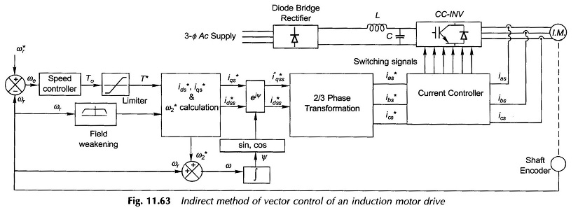
The Vector Control of Induction Motor method is block diagram form is illustrated in Fig. 11.63 certain crucial steps are as follows.
From the motor speed signal (ωr) and desired speed (ω*r) the error ωe is determined. Speed controller calculates the motor torque (To) needed to correct the speed which is passed through a Limiter to determine torque signal T*.
In a parallel Field Weakening block the motor speed ωr generates another signal.
These two signals are employed to calculate i*ds and i*qs (ideal quadrature currents) and a speed correction ω*2.
ω = ωr + ω*r is integrated which is then used to find the transformation ejψ. This transformation carried out on ( i*ds , i*qs ) gives the final ideal set ( i*dss , i*qss ).
2/3 phase transformation on (i*dss , i*qss) yields the ideal stator current (i*as, i*bs, i*cs).
The measured stator currents (ias, ibs, ics) are compared with (i*as, i*bs, i*cs) by the current controller and the six signals generated control the currents fed to the induction motor.
The above is a simplified explanation of the vector control algorithm for the induction motor control.
In the Vector Control of Induction Motor, the rotor flux is regulated through the stator windings current control. For regulating the rotor flux, the knowledge of its position is also desired. Rotor flux position is either sensed or estimated. Therefore, depending upon the methodologies adopted for assessing the rotor flux vector position, the vector control is termed either as a direct vector control or an indirect vector control.
