Voltage Regulation Formula of Transformer:
Voltage Regulation Formula – Constant voltage is the requirement of most domestic, commercial and industrial loads. It is, therefore, necessary that the output voltage of a transformer must stay within narrow limits as the load and its power factor vary. This requirement is more stringent in distribution transformers as these directly feed the load centres. The voltage drop in a transformer on load is chiefly determined by its leakage reactance which must be kept as low as design and manufacturing techniques would permit.
The figure of merit which determines the voltage drop characteristic of a transformer is the voltage regulation. It is defined as the change in magnitude of the secondary (terminal) voltage, when full-load (rated load) of specified power factor supplied at rated voltage is thrown off, i.e. reduced to no-load with primary voltage (and frequency) held constant, as percentage of the rated load terminal voltage. In terms of symbols
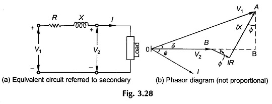
Figure 3.28(a) shows the transformer equivalent circuit referred to the secondary side and Fig. 3.28(b) gives its phasor diagram. The voltage drops IR and IX (as shown in the phasor diagram) are very small in a well-designed transformer. As a result the angle δ between V1 and V2 is of negligible order, so that
When the load is thrown off
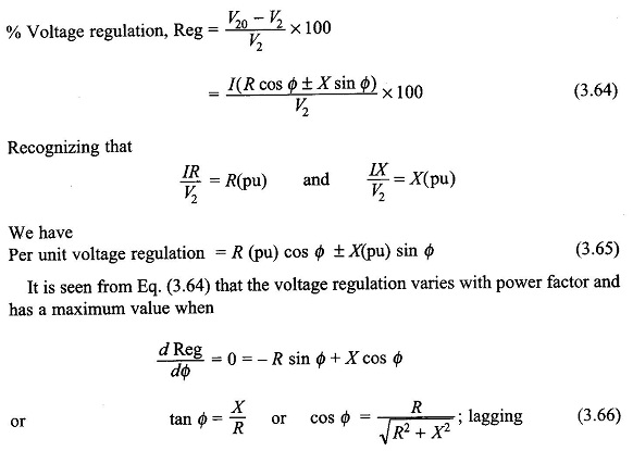
where I is the full-load secondary current and V2, the full-load secondary voltage (equal to the value of V2 (rated)). Thus
Equation (3.66) implies that voltage regulation is the maximum when the load power factor (lagging) angle has the same value as the angle of the equivalent impedance. From Eq. (3.65), the Voltage Regulation Formula is zero when
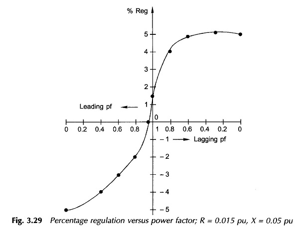
For Φ (leading) larger than that given by Eq. (3.66), the Voltage Regulation Formula is negative (i.e. the secondary full-load voltage is more than the no-load voltage).
The complete variation of % regulation with power factor is shown in Fig. 3.29.


